Display device and electronic equipment

A display device and technology for displaying light, which can be used in measuring devices, radiation control devices, devices with multiple detectors, etc., and can solve the problems of difficult size reduction and high cost

Inactive Publication Date: 2010-01-27
JAPAN DISPLAY INC
View PDF6 Cites 7 Cited by
  • Summary
  • Abstract
  • Description
  • Claims
  • Application Information

AI Technical Summary

Problems solved by technology

[0004] However, the above-mentioned display device having a coordinate input function is difficult to reduce in size, resulting in high cost compared with general display devices

Method used


Image

  • Display device and electronic equipment
  • Display device and electronic equipment
  • Display device and electronic equipment

Examples


Embodiment Construction

[0039] Preferred embodiments of the present invention will be described below with reference to the accompanying drawings.

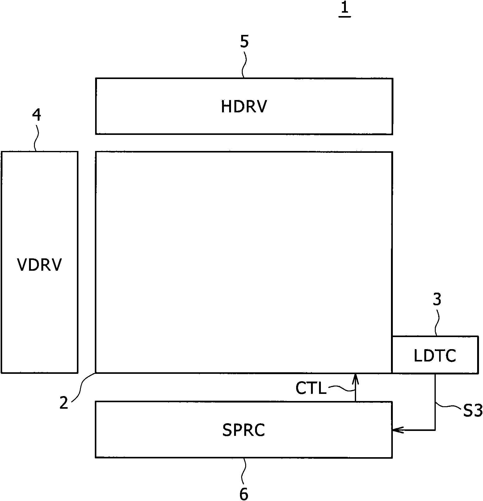
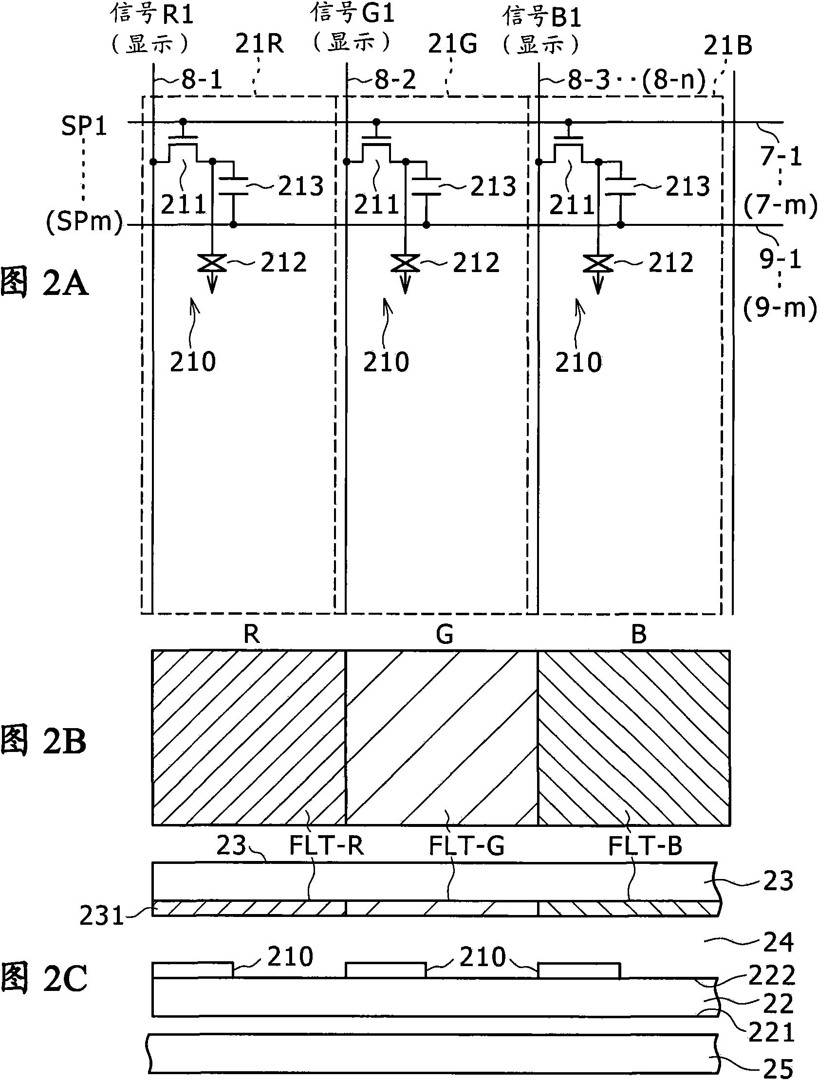
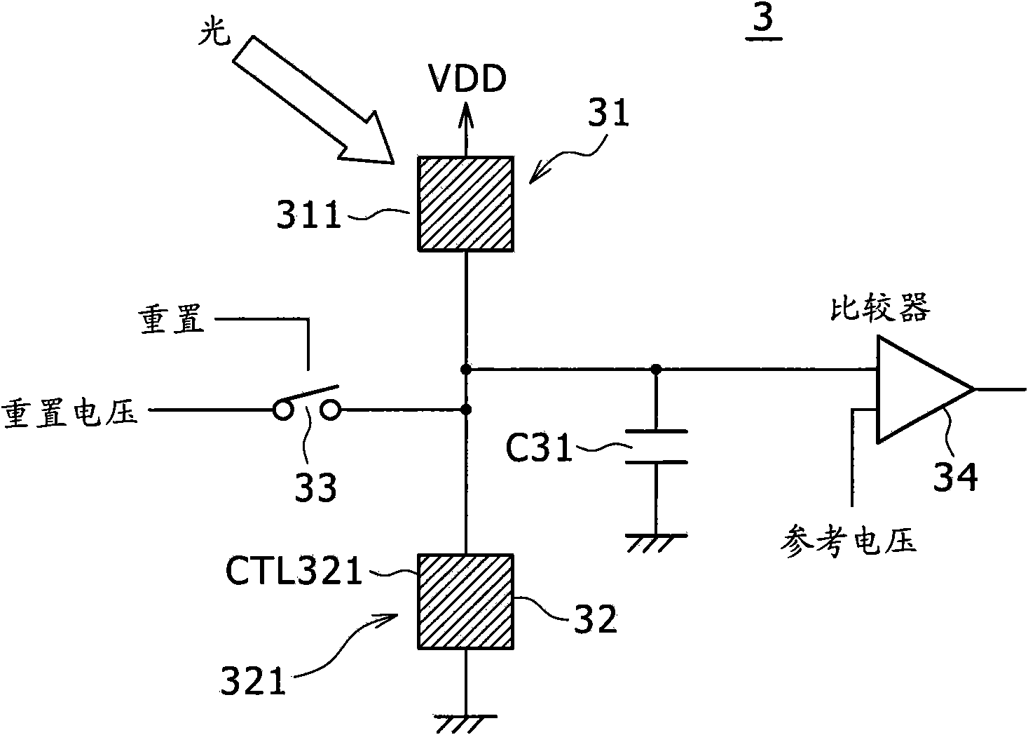
[0040] figure 1 is a block diagram illustrating a configuration example of a liquid crystal display device according to one embodiment of the present invention. Figures 2A to 2C is description figure 1 A diagram showing a configuration example of an effective display area of ​​a liquid crystal display device. Figure 2A Describes the matrix arrangement of cells. Figure 2B is the floor plan of the unit. Figure 2C is a cross-sectional view of the unit. image 3 is a diagram illustrating a configuration example of a photodetection circuit according to the present embodiment.

[0041] like figure 1 As shown, a liquid crystal display device 1 includes an effective display area portion (image display portion) 2 serving as a display portion, a photodetection portion (LDTC) 3, a vertical drive circuit (VDRV) 4, a horizontal drive circuit (HDRV) 5, and a...


PUM


Abstract

The invention discloses a display device and electronic equipment. Disclosed herein is a display device, including: a first photosensor section; second photosensor section; and signal processing section, wherein the light-shielding film is formed in the same layer as that on the substrate having a light-shielding function so as to be associated with the light-receiving element of the second photosensor section.

Description

technical field [0001] The present invention relates to a display device having a photosensor in a display pixel portion and a frame area around a display surface, and an electronic device using the display device. Background technique [0002] A technique is known in which high screen luminance is ensured in the case of high ambient illuminance and low screen luminance is secured in the case of low ambient illuminance by detecting the illuminance of external light with a photosensor. This technology not only provides an easy-to-view screen, but also contributes to reducing power consumption of a backlight system in the case of a liquid crystal display device that displays images through a backlight. In addition, this technology helps to extend the battery life of mobile applications such as mobile phones. Accordingly, various such techniques are being researched. [0003] In addition, several technologies have been proposed, among which are designed to provide a display d...

Claims


Application Information

Patent Timeline
Patent Type & Authority Applications(China)
IPC IPC(8): G02F1/133H01L27/144
CPCG02F1/13338G01J1/4228G01J1/46G09G3/3406G01J1/32G06F3/0421G02F1/136209G09G2320/0626G01J1/4204G02F1/13318G09G2360/144G06F3/0412
Inventor 大谷夏树
Owner JAPAN DISPLAY INC
Why Eureka
Try Eureka