Helicopter with separated tip jet device and main rotor wing

A jet wing and main rotor technology, which is applied in the field of jet wing tip helicopters, can solve the problems of high efficiency, reduced main rotor speed, and reduced main rotor tip propulsion efficiency.

Inactive Publication Date: 2010-02-03
余志刚
View PDF0 Cites 3 Cited by
  • Summary
  • Abstract
  • Description
  • Claims
  • Application Information

AI Technical Summary

Problems solved by technology

[0003] In order to overcome the problem that the existing jet wingtip helicopter must reduce the working efficiency of the ramjet engine on the wingtip in order to ensure the efficiency of its main rotor, the invention provides a helicopter in which the jet wingtip device is separated from the main rotor
[0005] The invention has the beneficial effects of solving the problem that the jet wingtip device (ramjet) of the known jet wingtip helicopter has high efficiency at supersonic speed and the propulsion efficiency of the main rotor wingtip linear velocity drops sharply at supersonic speed Problem: The power wing installed with the jet wing tip device is separated from the main rotor, and the speed of the main rotor is reduced by a reducer, so that the jet wing tip device is at a supersonic speed and the linear velocity of the main rotor wing tip is at a subsonic speed; the jet wing The working efficiency of the tip device and the propulsion efficiency of the main rotor have reached the best state

Method used


Image

  • Helicopter with separated tip jet device and main rotor wing
  • Helicopter with separated tip jet device and main rotor wing
  • Helicopter with separated tip jet device and main rotor wing

Examples


Embodiment Construction

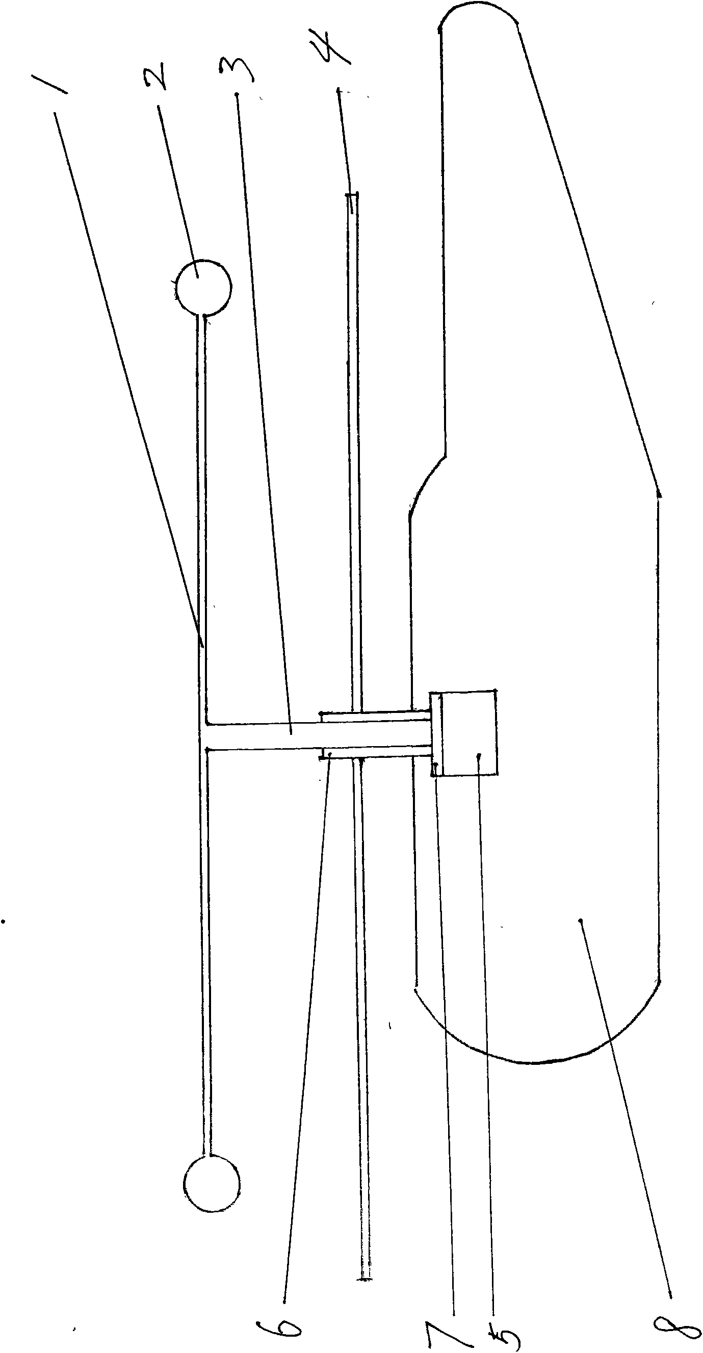
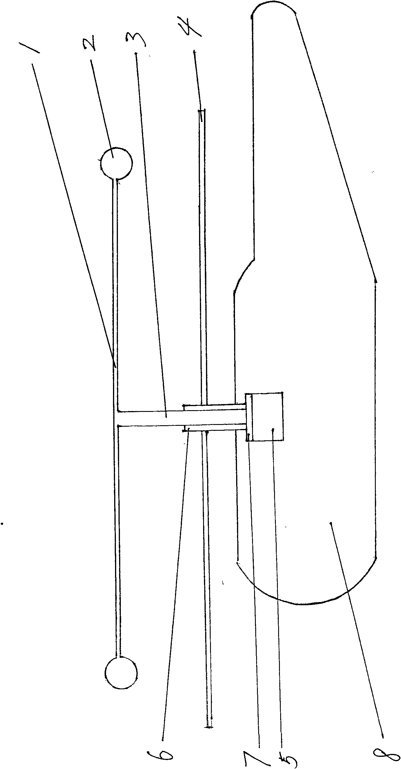
[0011] exist figure 1 Among them, 1. power wing, 2. jet wingtip device, 3. power wing output shaft, 4. main rotor, 5. reducer, 6. reducer output sleeve shaft, 7. clutch, 8. body.

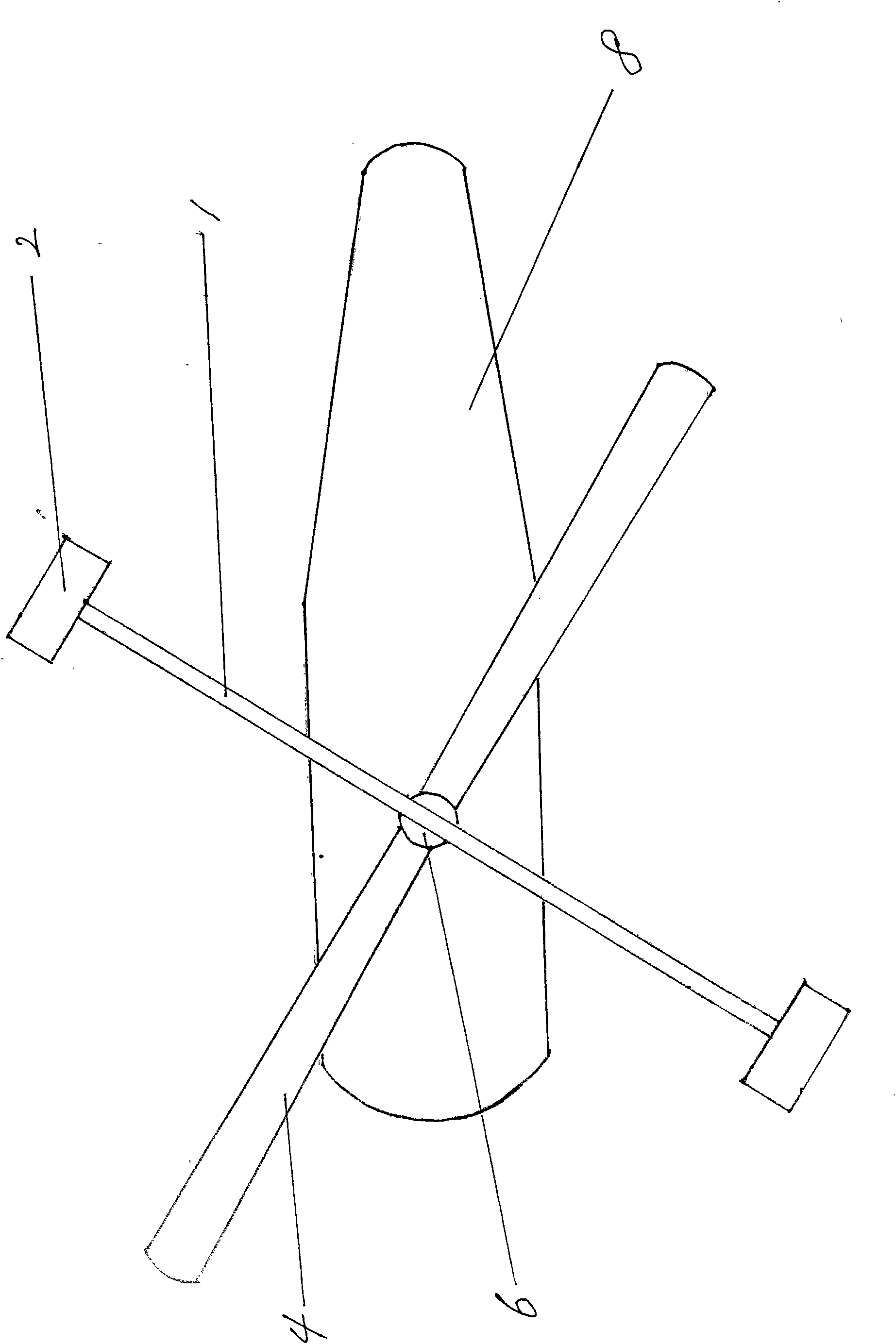
[0012] exist figure 2 Among them, 1. power wing, 2. jet wingtip device, 4. main rotor, 6. reducer output shaft, 8. body.

[0013] exist image 3 and Figure 4 Among them, the jet wing tip device (2) is arranged at both ends of the power wing (1), and the power wing output shaft (3) is located at the horizontal center point of the power wing (1) and fixed; the power wing output shaft (3) is connected with the reducer (5) is connected, and the output of reducer (5) is reducer output shaft (6), and reducer output sleeve shaft (6) links to each other with main rotor (4); Jet wing tip device (2) makes power wing (1 ) to rotate and drive the power wing output shaft (3) to rotate, the speed reducer (5) reduces the speed of the power wing output shaft (3) and outputs it to the speed reducer output slee...


PUM


Abstract

The invention discloses a helicopter with a separated tip jet device and a main rotor wing. The tip jet device is arranged at the front end of a power wing, an output shaft of the power wing is connected with the main rotor wing through a decelerator system so that the rotating speed of the main rotor wing is lower than that of the power wing; and the output shaft of the power wing, a deceleratorand an output shaft of the decelerator are hinged with a helicopter body. The helicopter solves the problem that the tip jet device of the known tip jet type helicopter has high efficiency at supersonic speed while the propulsive efficiency of the main rotor wing declines when the wing tip linear speed is at the supersonic speed; and the working efficiency of the tip jet device and the propulsiveefficiency of the main rotor wing achieve best states.

Description

technical field [0001] The invention relates to a jet-tip (tip jet) helicopter, in particular to a helicopter adopting the technique of separating a jet-tip device from a main rotor. Background technique [0002] At present, known jet wingtip formula helicopter, its tip jet (tip jet) device is arranged on the two ends of main rotor, and propels main rotor to rotate by jet tip jet; Many jet tip devices adopt ramjet , its best working efficiency is in the case of supersonic speed; but when the linear velocity of the main rotor end of the helicopter reaches or exceeds the speed of sound, the propulsion efficiency of the main rotor will drop sharply; therefore in order to ensure the propulsion efficiency of the main rotor, it is necessary to use The linear velocity of the main rotor endpoint is lower than the speed of sound, so that the ramjet on the tip of the main rotor is placed in a subsonic motion state, thereby reducing the working efficiency of the ramjet on the tip of th...

Claims


Application Information

Patent Timeline
Patent Type & Authority Applications(China)
IPC IPC(8): B64D27/16B64C27/04
Inventor 余志刚
Owner 余志刚
Why Eureka
Try Eureka