Method for packaging high-furnace cooling wall

A packaging method and cooling stave technology, applied in the field of packaging and transportation of large and medium-sized parts and components of metallurgical equipment, can solve problems such as scrapping, cooling stave damage, economic loss, etc.

Inactive Publication Date: 2010-02-03
周传禄
View PDF0 Cites 2 Cited by
  • Summary
  • Abstract
  • Description
  • Claims
  • Application Information

AI Technical Summary

Problems solved by technology

[0002] The blast furnace cooling stave is a key component of the ironmaking blast furnace. According to its installation in the blast furnace, it is divided into six walls: inner, outer, upper, lower, left, and right. The inner and outer walls are centered on the center line of the blast furnace. The concentric arc surface is the key working surface of the stave. The inner wall faces the furnace core and is arranged in the form of a plane or inlaid bricks. A group or groups of cooling water pipes are installed on the outer wall to force water to cool the stave of the bl

Method used


Image

  • Method for packaging high-furnace cooling wall
  • Method for packaging high-furnace cooling wall
  • Method for packaging high-furnace cooling wall

Examples


Embodiment 1

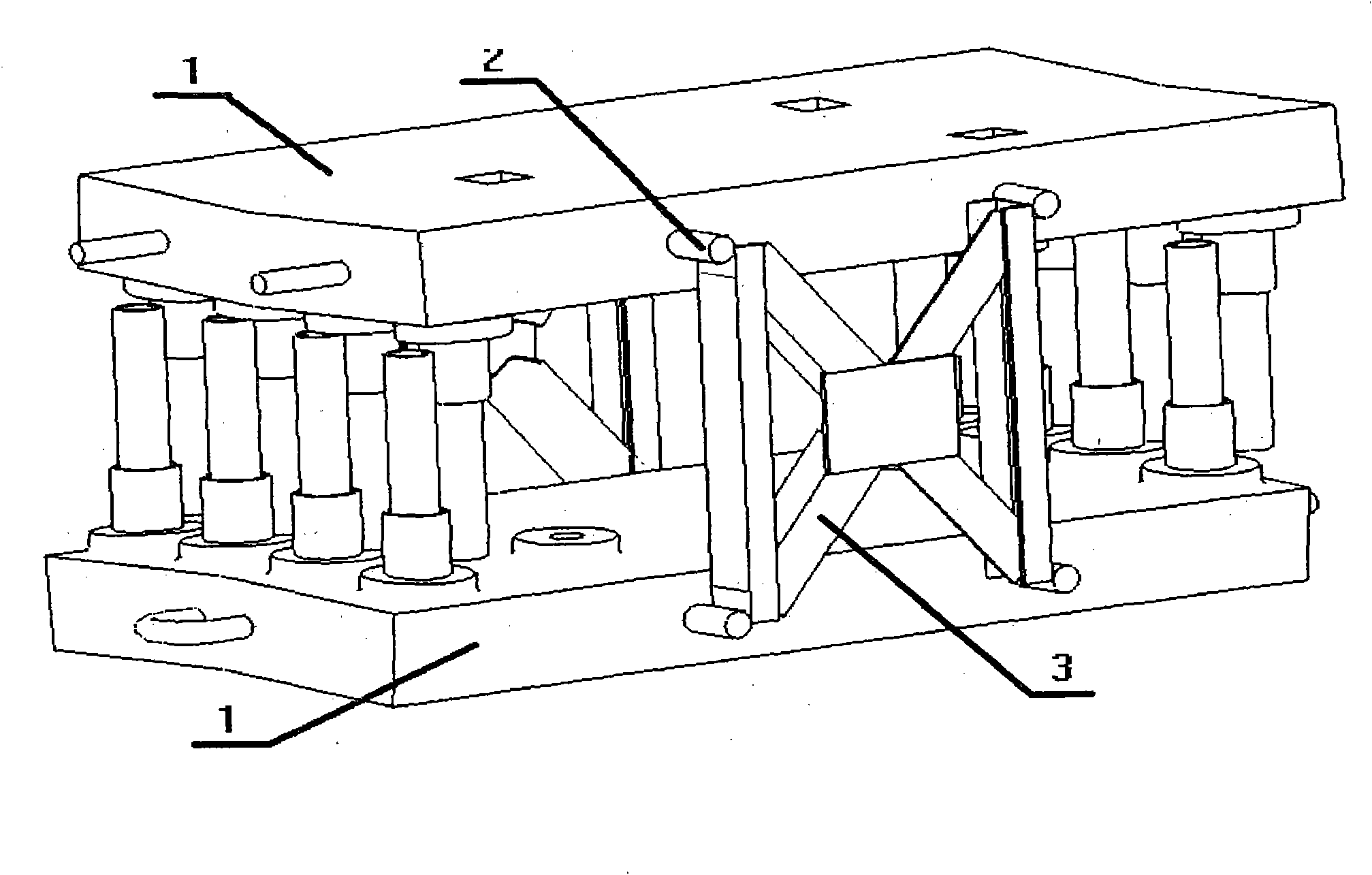
[0014] Such as figure 1 As shown in the perspective view of blast furnace stave packaging structure embodiment 1, the outer walls of two blast furnace staves 1 are stacked back to back so that the inlet and outlet pipes are protected by the two staves. Figure 5 The prefabricated packaging bracket 3 is installed and welded on the packaging cross arm 2 on the stave, so that the two staves form a solid whole with the outer wall convex arc surface inside the inlet and outlet pipes and the inner wall concave arc surface outward. To ensure the safety and reliability of stacking, transportation, loading and unloading; among them, the stave packaging cross arm is made of round steel, according to Figure 4 The cross-arm layout of the blast furnace stave packaging is processed and cast together with the blast furnace stave body to ensure a firm and effective fulcrum for the packaging bracket.

Embodiment 2

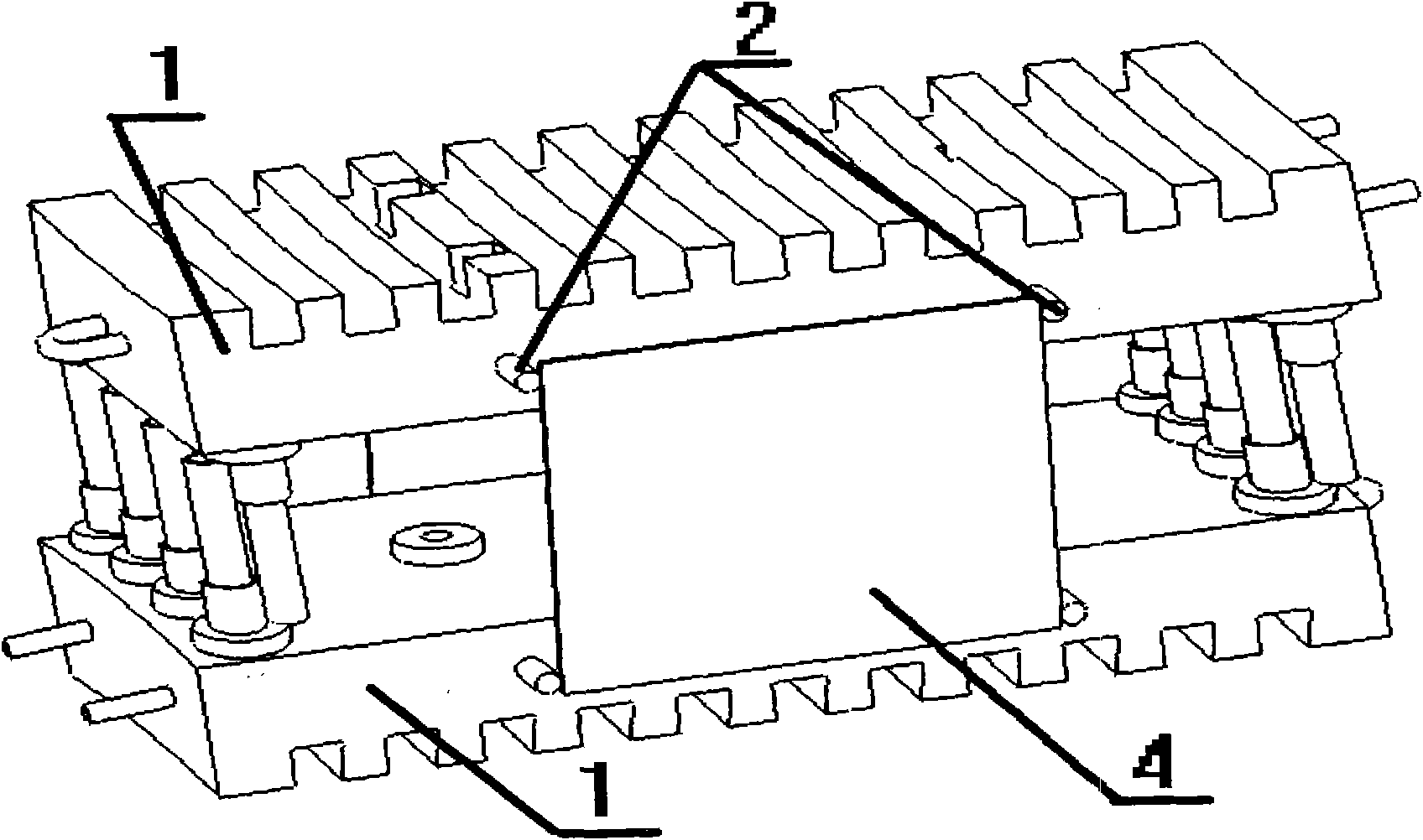
[0016] Such as figure 2 As shown in the perspective view of blast furnace stave packaging structure embodiment 2, the outer walls of two blast furnace staves 1 are stacked back to back so that the inlet and outlet pipes are protected by the two staves. Figure 6 Steel plate packaging bracket diagram The prefabricated packaging bracket 3 is installed and welded on the packaging cross arm 2 on the cooling wall, so that the two cooling walls form a solid whole with the outer wall convex arc surface inside the inlet and outlet pipes and the inner wall concave arc surface outward. To ensure the safety and reliability of stacking, transportation, loading and unloading; among them, the stave packaging cross arm is made of section steel, according to Figure 4 The cross-arm layout of the blast furnace stave packaging requires processing, and it is cast together with the blast furnace stave body to ensure that the packaging bracket has a firm and effective fulcrum.

Embodiment 3

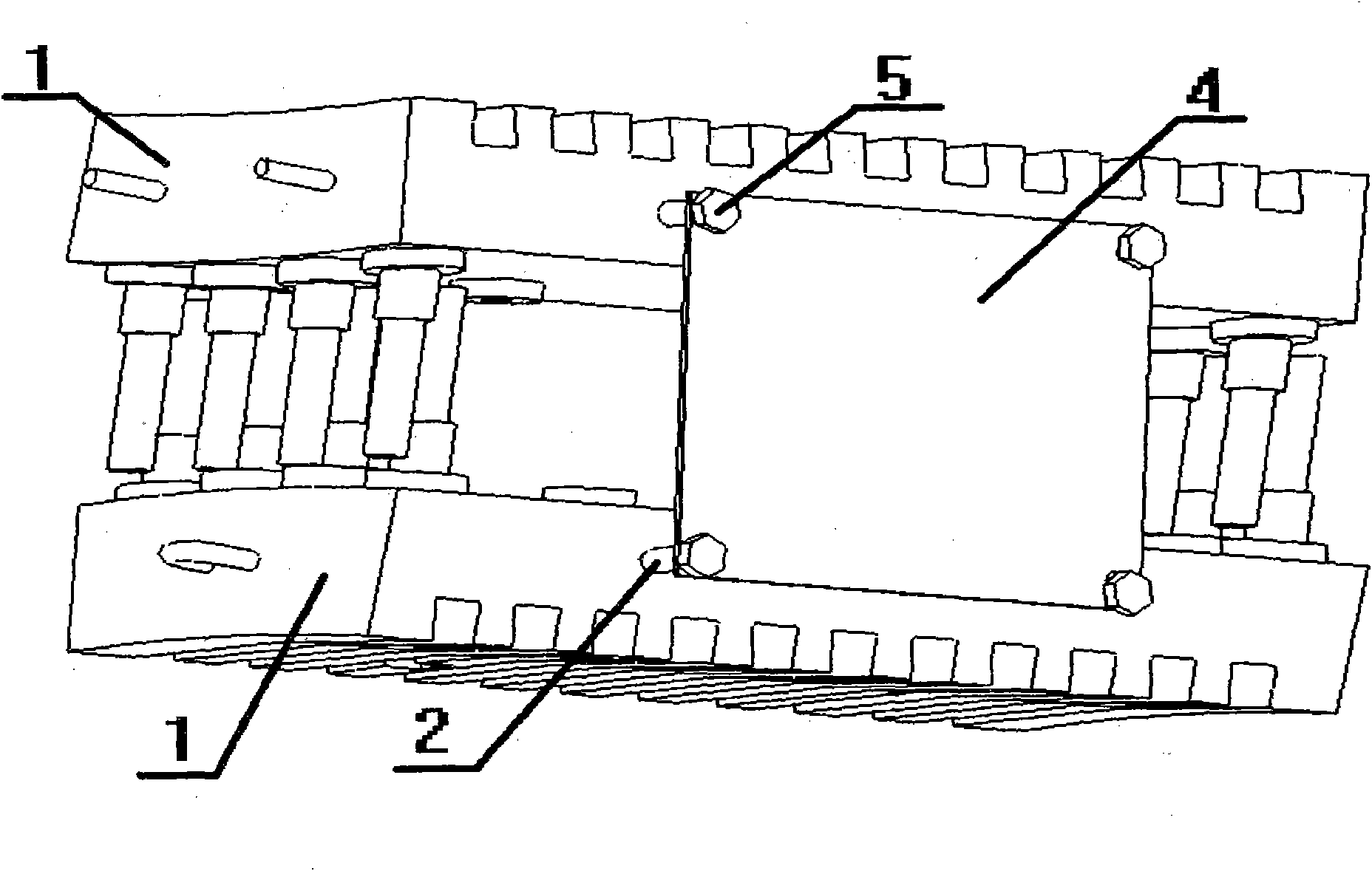
[0018] Such as image 3 As shown in the third perspective view of blast furnace stave packaging structure embodiment, the outer walls of two blast furnace staves 1 are stacked back to back so that the inlet and outlet pipes are protected by the two staves. Steel processed into bolts, press Figure 4 The cross-arm layout drawing of blast furnace stave packaging requires casting together with the blast furnace stave body. press Figure 7 Steel plate packaging bracket diagram (bolt fastening) The prefabricated packaging bracket 3 is installed on the cooling wall packaging cross arm 2, and fastened together with nuts, so that the two pieces of cooling walls form a convex arc surface on the outer wall. The concave arc faces outwards as a solid whole to ensure safe and reliable stacking, transportation, loading and unloading.


PUM


Abstract

The invention relates to a method for packaging a high-furnace cooling wall, comprising the following steps: overlapping the outer walls of two high-furnace cooling walls back to back so that an inletand outlet pipe opening is protected by the two cooling walls; installing a prefabricated packaging bracket on a packaging cross arm of each cooling wall so that the two cooling walls form a firm integrity with an inward outer wall convex cambered surface inlet and outlet pipe opening and an outward inner wall concave cambered surface to ensure safety and reliable storage, transportation as wellas assembly and disassembly, wherein the packaging cross arm of each cooling wall is made of round steel or profile steel; the packaging cross arms of the two cooling walls are respectively arranged at the left side and the right side of the cooling wall with a space of 20-90 percent of the length of the cooling wall, and cast together with a high-furnace cooling wall body to ensure that the packaging bracket obtains a firm and effective fulcrum; the packaging bracket of the cooling wall is made of profile steel or the whole block of steel plate and welded with the packaging cross arm of the cooling wall or fastened together with a screw.

Description

technical field [0001] The invention relates to a method for packaging cooling staves of a blast furnace, and belongs to the field of packaging and transportation of large and medium-sized parts of metallurgical equipment. Background technique [0002] The blast furnace cooling stave is a key component of the ironmaking blast furnace. According to its installation in the blast furnace, it is divided into six walls: inner, outer, upper, lower, left, and right. The inner and outer walls are centered on the center line of the blast furnace. The concentric arc surface is the key working surface of the stave. The inner wall faces the furnace core and is arranged in the form of a plane or inlaid bricks. A group or groups of cooling water pipes are installed on the outer wall to force water to cool the stave of the blast furnace when the blast furnace is working. Safe operation of the blast furnace; depending on the location of the blast furnace model, the cooling stave ranges from...

Claims


Application Information

Patent Timeline
IPC IPC(8): B65D71/50C21B7/10
Inventor 姚朝胜魏新民衣忠德刘洪亮马平胜周传禄
Owner 周传禄
Why Eureka
Try Eureka