
Hydraulic three-gear increaser

A hydraulic, weak gear technology, used in clutches, components with teeth, belts/chains/gears, etc., can solve problems such as high cost and complex manufacturing, and achieve a wide range of applications.

Inactive Publication Date: 2010-02-03
熊涔博
View PDF0 Cites 0 Cited by
  • Summary
  • Abstract
  • Description
  • Claims
  • Application Information

AI Technical Summary

Problems solved by technology

Existing mechanical CVTs are complicated to manufacture, costly, and can only be used in light-duty vehicles

Method used


Image

  • Hydraulic three-gear increaser

Examples


Embodiment Construction

[0014] The structure and function of the present invention will be described below in conjunction with the drawings

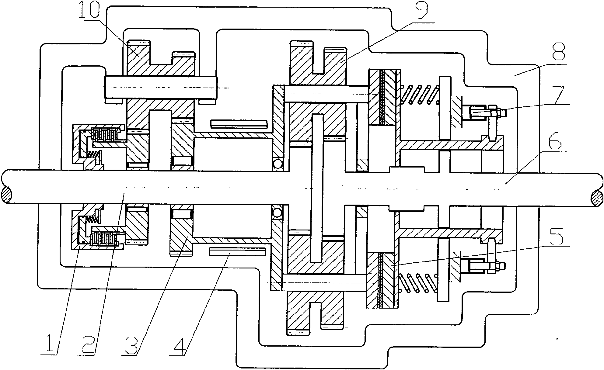
[0015] see figure 1 , the power of the gearbox is input from the output shaft to the input gear shaft 2 of the booster. In general, the booster is in direct gear. At this time, the multi-plate clutch 1 and the band brake 4 are released, and the single-plate clutch 5 is in the Compressed under the action of the spring, the double planetary gear 9 locks the input gear shaft 2 and the output gear shaft 6 as one, and the power directly passes through the gear booster without changing the speed, and the gear is the gear of the gearbox.

[0016] When the multi-disc clutch 1 and the single-disc clutch 5 are released, the band brake 4 brakes the ring gear sleeve 3, and the upshifter is in a weak gear, and the power will be transmitted to the output gear shaft through the braked double planetary gear 9 6. The transmission ratio is greater than 1, which plays the role o...


PUM


Abstract

The invention discloses a hydraulic three-gear increaser, which uses a combination of a single plate clutch, a multi-plate clutch and a band brake to control a transmission line through a hydraulic system so that the gear increaser has three gears, namely a weak gear, a direct gear and a strong gear. Therefore, the gears of a gear box are increased thrice; the gear shift of the gear increaser doesnot need to step on a vehicle clutch and is realized by directly using a hydraulic gear shifting valve, so the gear shifting operation is simple, and can achieve the effect of quasi stepless speed change and improve the economy and dynamic property of vehicles.

Description

technical field [0001] The invention relates to a three-gear booster, which is suitable for various automobiles, can triple the number of gears of the vehicle, and improves the economy and power of the vehicle. Background technique [0002] At present, the gearboxes used on ordinary manual transmission cars and light and medium-sized trucks generally only have 3 to 6 forward gears and one reverse gear. The manufacture of existing mechanical continuously variable transmissions is relatively complicated, the cost is high, and it can only be used for light vehicles. For ordinary manual transmission cars and light and medium-sized trucks, appropriately increasing the gear without increasing the shifting intensity will improve the economy and power of the vehicle. Contents of the invention [0003] The purpose of the present invention is to provide a hydraulic three-speed upshifter, which belongs to an assembly and can be applied to various ordinary manual transmission cars an...

Claims


Application Information

Patent Timeline
Patent Type & Authority Applications(China)
IPC IPC(8): F16H61/00F16H61/06F16D48/02
Inventor 熊涔博
Owner 熊涔博
Learn More