Dehumidifier

A dehumidifier and cabinet technology, which is used in household heating, lighting and heating equipment, space heating and ventilation, etc., can solve the problems of unfavorable indoor air temperature and humidity, small contact area, etc. The effect of the air intake area

Inactive Publication Date: 2010-02-03
LG ELECTRONICS (TIANJIN) APPLIANCES CO LTD
View PDF6 Cites 13 Cited by
  • Summary
  • Abstract
  • Description
  • Claims
  • Application Information

AI Technical Summary

Problems solved by technology

[0006] However, in the dehumidifier of the prior art, the sending fan 5a is a centrifugal fan, and the humid air is sucked in from the back of the dehumidifier casing 1, flows through the evaporator 2 and the condenser 3 of the flat plate structure, and the dehumidified air passes through the front front of the dehumidifier. Panel 7 discharges to external
Since the evaporator 2 and condenser 3 of the flat plate structure have a small contact area with the air, and there are only suction ports located on the back side, it is not conducive to the balance of indoor air temperature and humidity

Method used


Image

  • Dehumidifier
  • Dehumidifier
  • Dehumidifier

Examples


Embodiment Construction

[0016] Below in conjunction with accompanying drawing and specific embodiment the present invention is described in further detail:

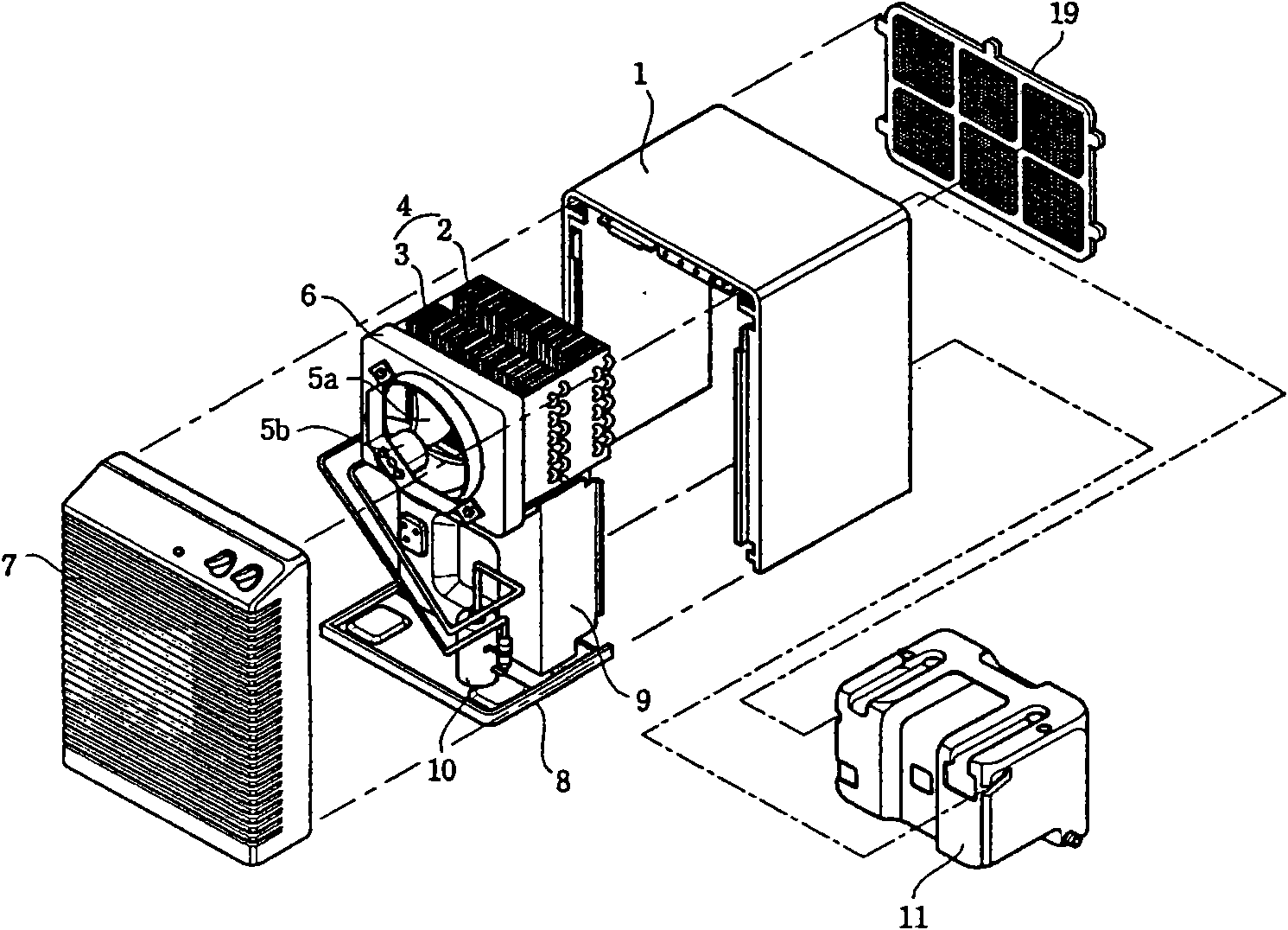
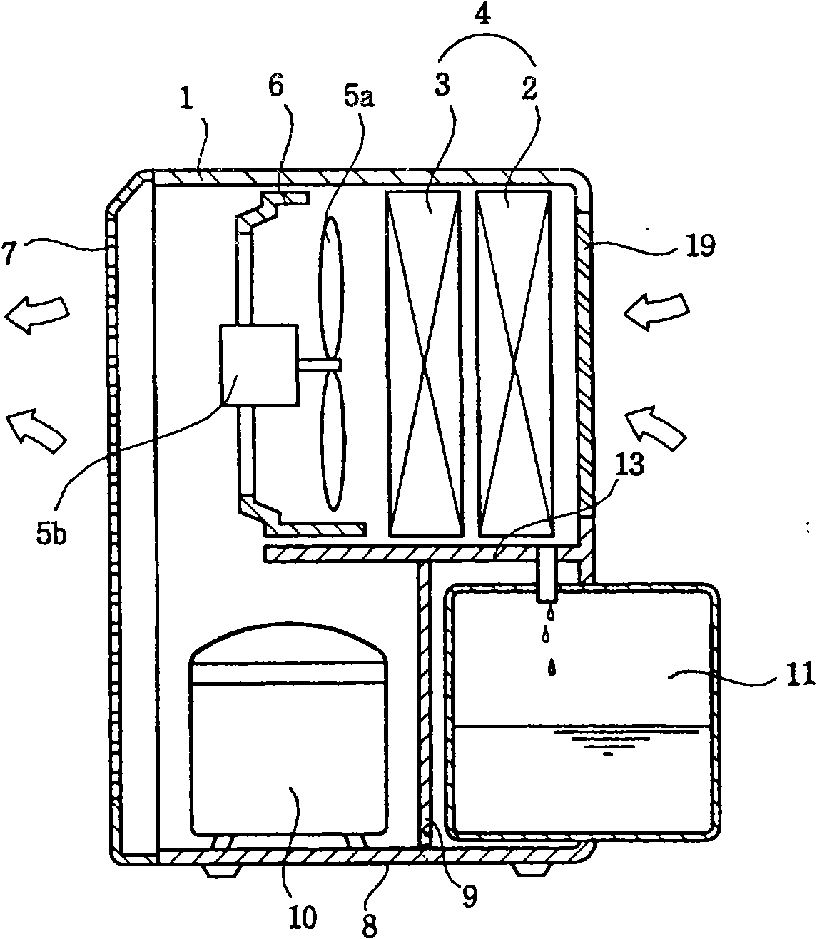
[0017] For the same parts of the dehumidifier of the present invention and the prior art, reference may be made to the prior art, and the same symbols shall be used.

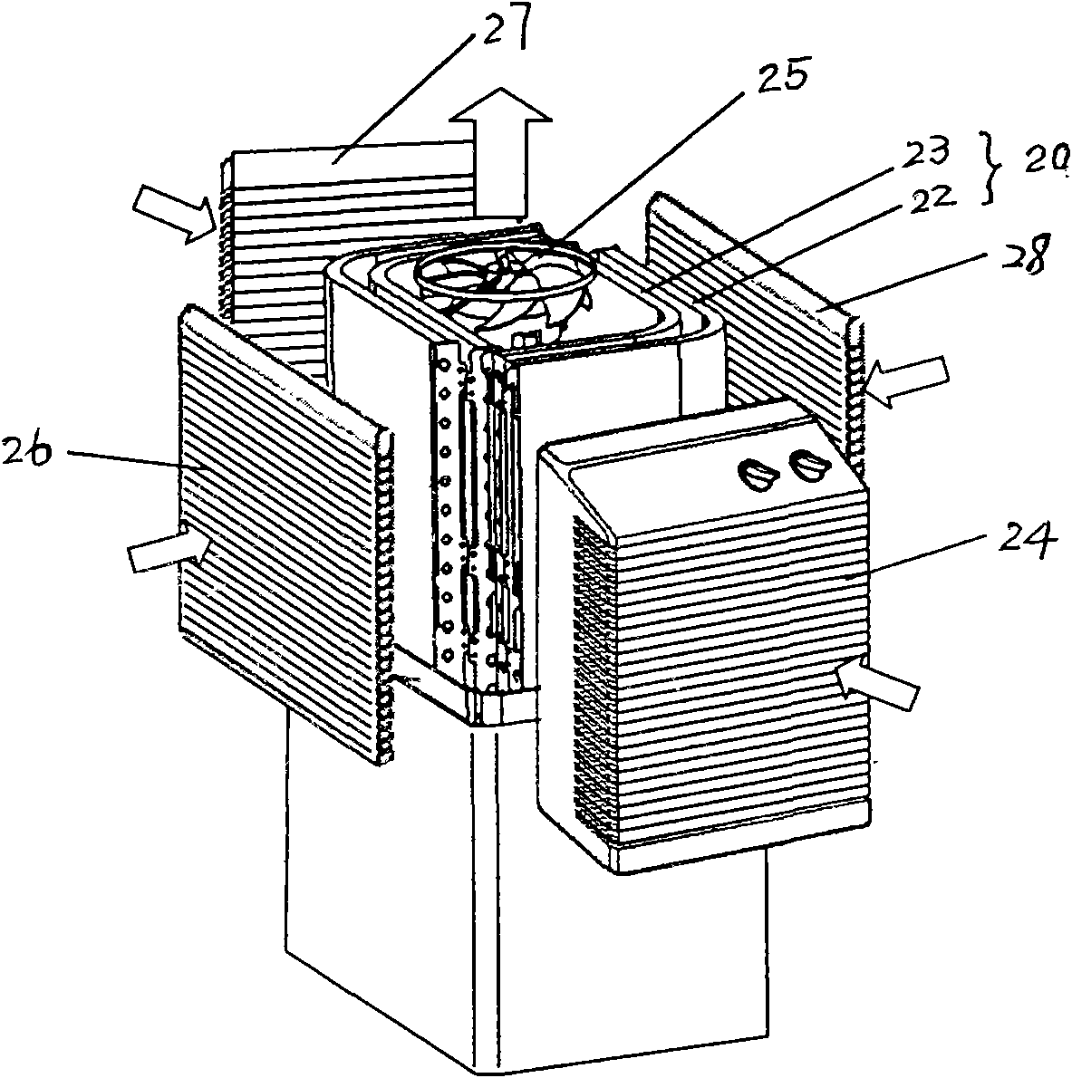
[0018] like image 3 As shown, the dehumidifier of the present invention includes: a casing formed with an air inlet and an air outlet, and the air inlet is located on four sides of the casing, namely the front casing 24, the rear casing 27, and the left casing 26 and the right side casing 28, the air outlet is positioned at the top of the casing (not shown), the four sides of the casing are divided into upper and lower parts in this example, and the air inlet is positioned at the upper part of the four sides of the casing, of course The four sides of the casing can also be integrally formed. The heat exchanger 20 forms a circle along the inner side of the casing with the air su...


PUM


Abstract

The invention discloses a dehumidifier, which comprises a shell, a heat exchanger, a water collecting barrel, an air supply fan, a motor and a compressor, wherein the shell is provided with air suction inlets and air outlet; the heat exchanger consists of an evaporator and a condenser; the water collecting barrel stores the falling condensate water generated on the surface of the evaporator; the air supply fan and the motor suck indoor air into the shell and then exhaust the air into a room; the compressor compresses the air; the air suction inlets are positioned on four sides of the shell; the air outlet is positioned on the top of the shell; the heat exchanger is formed into a circle along the inner side of the periphery of the shell with the air suction inlets; and the center enclosed by the heat exchanger is provided with an axial flow fan and an axial flow motor which suck the indoor air into the shell and then exhaust the air into the room. The bent heat exchanger replaces a plate heat exchanger to increase the air inlet area. The axial flow fan ensures air flow directions of inlet air from four sides and outlet air on the upper part.

Description

technical field [0001] The invention relates to a dehumidifier, in particular to a dehumidifier which fully increases the air intake area, enhances the heat exchange effect, and is beneficial to the overall temperature and humidity balance of indoor air. Background technique [0002] like figure 1 , 2 As shown, the dehumidifier in the prior art includes: a casing 1 that constitutes the appearance of the left and right sides and the top, and the front, rear and bottom surfaces are open; the evaporator 2 and the condenser 3 that are arranged inside the casing 1 The heat exchanger 4 for dehumidification; the compressor 10 for compressing the refrigerant circulating in the evaporator 2 and the condenser 3; it is arranged in front or behind the heat exchanger 4 and generates wind power to suck the indoor air into the casing 1 and then discharged to the indoor blower fan 5a and motor 5b; arranged in front of the casing 1, so that the dehumidified air flowing through the heat exc...

Claims


Application Information

Patent Timeline
Patent Type & Authority Applications(China)
IPC IPC(8): F24F1/02F24F3/14
Inventor 葛住军张金兰鲍长桥卢大为
Owner LG ELECTRONICS (TIANJIN) APPLIANCES CO LTD
Why Eureka
Try Eureka