Detecting device for detecting IGBT

A test device and test circuit technology, applied in the direction of single semiconductor device testing, etc., can solve the problems of long cycle and large investment, and achieve the effect of simple measurement method, low energy consumption and clear interface

Active Publication Date: 2010-02-03
天津华云自控股份有限公司
View PDF0 Cites 25 Cited by
  • Summary
  • Abstract
  • Description
  • Claims
  • Application Information

AI Technical Summary

Problems solved by technology

To measure various technical parameters of IGBT, it is necessary to purchase a complete set of test instruments and test benches from abroad, and to build a special test room. The investment is large, the cycle is long, and professional test personnel need to be trained. General enterprises cannot afford huge capital investment. However, there is no simple and easy way to measure whether the IGBT is good or bad in actual production.

Method used


Image

  • Detecting device for detecting IGBT
  • Detecting device for detecting IGBT
  • Detecting device for detecting IGBT

Examples


Embodiment Construction

[0015] Below in conjunction with the accompanying drawings and preferred embodiments, the specific implementation methods, structures, features and functions provided by the present invention will be described in detail as follows.

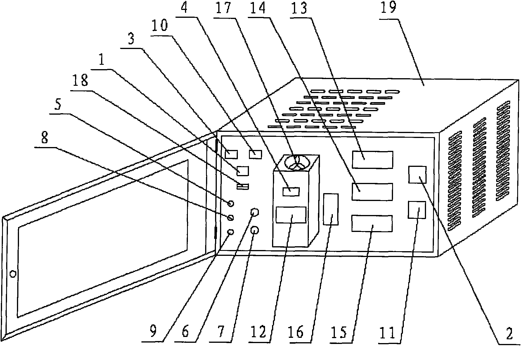
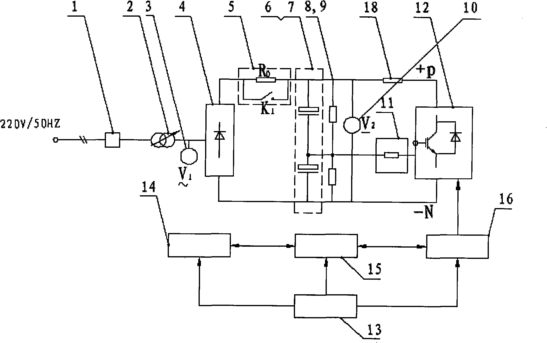
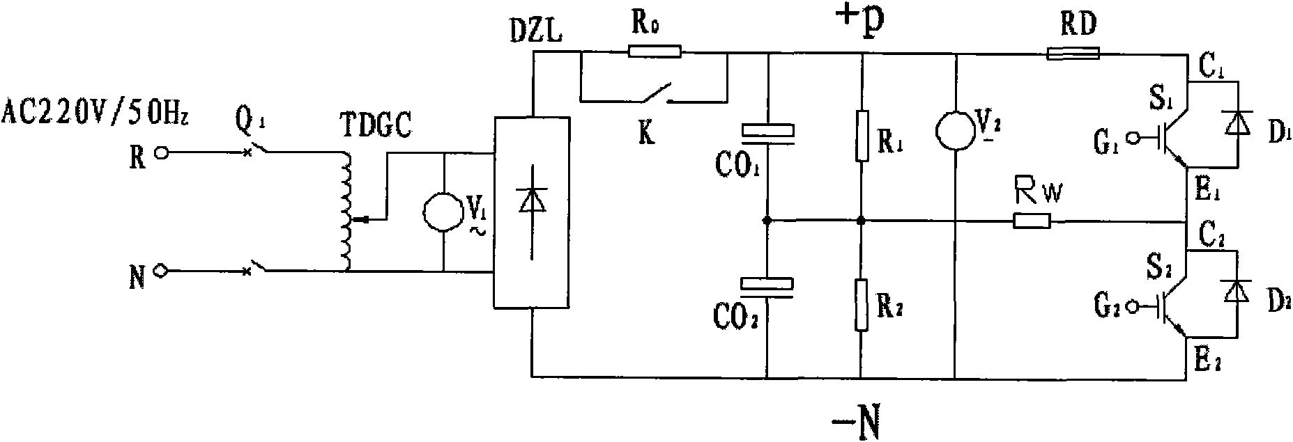
[0016] See Figure 1~3 , a test device for detecting IGBTs, comprising a housing and a test circuit housed in the housing, the test circuit consists of a power board, an I / O board, a central processing unit, a drive module, a micro circuit breaker, an autocoupler Composed of a voltage regulator and rectification, filtering, and inverter circuits, the single-phase 220V, 50Hz AC power supply is connected in series to the primary side of the auto-coupling voltage regulator 2 through the micro-circuit breaker 1, and the secondary side of the auto-coupling voltage regulator is connected to the AC voltmeter in parallel V 1 3 and input the AC voltage to the diode rectifier bridge module 4, after the positive terminal of the diode rectifier bridge module...


PUM


Abstract

The invention relates to a detecting device for detecting IGBT, comprising a shell and a testing circuit internally installed in the shell. The testing circuit consists of a power board, an I/O board,a central processing unit, a driver module, a micro breaker, an automatic coupling voltage regulator, a rectifying circuit, a filter circuit and an inverter circuit. A single-phase 220V, 50Hz alternating current power supply source is connected with the original edge of the automatic coupling voltage regulator in series; the secondary edge of the automatic coupling voltage regulator is connectedwith an AC voltmeter in parallel and inputs alternating voltage into a diode rectifier bridge module; the positive end of the automatic coupling voltage regulator is connected with a limit resistor inseries, is connected with a filter capacitor, a equalizing resistor and a DC voltmeter in parallel, and is connected with a fuse in series; +P and -N bus is connected with an inverse bridge formed byan IGBT module in parallel; the output end of the inverse bridge is connected with an output resistor; and the other end of the resistor is connected with the middle connecting point of the equalizing resistor. By detecting the PWM waveform of the output resistor, the detecting device can ensure the condition of the IGBT, has simple and easy measuring method, is time saving and labor saving, andis applicable to various IGBT detections.

Description

technical field [0001] The invention belongs to the field of testing devices for power electronic devices, and relates to a testing device for detecting IGBTs, which is suitable for testing IGBTs of power electronic devices, the main power device of frequency conversion speed control devices and inverters, and determines the quality of IGBTs through testing. and bad. Background technique [0002] With the development of power electronics technology, frequency conversion speed control devices and inverters composed of IGBTs have been widely used. However, in the process of producing frequency conversion speed control devices and inverters, how to detect whether the IGBT is good or bad has become a key process in production. To measure various technical parameters of IGBT, it is necessary to purchase a complete set of test instruments and test benches from abroad, and to build a special test room. The investment is large, the cycle is long, and professional test personnel nee...

Claims


Application Information

Patent Timeline
Patent Type & Authority Applications(China)
IPC IPC(8): G01R31/26
Inventor 归宝和
Owner 天津华云自控股份有限公司
Why Eureka
Try Eureka