
Vehicular metal absorber, vehicular bumper system, vehicular bumper absorber, and automobile bumper system

An absorber, metal technology, applied to bumpers, vehicle parts, vehicle safety arrangements, etc., can solve the problems of no convex and concave parts, complex structure, and inability to absorb collision energy, etc., to achieve the effect of protecting legs

Inactive Publication Date: 2010-02-03
UNIPRES CORP +1
View PDF7 Cites 14 Cited by
  • Summary
  • Abstract
  • Description
  • Claims
  • Application Information

AI Technical Summary

Problems solved by technology

However, as described later, since the energy absorption by the plastic deformation of the resin is small at the initial stage of deformation, there is a problem that the pedestrian cannot be protected with a short stroke when colliding with a pedestrian at a speed of 40 km / h, and the structure is complicated. not preferred by design
[0015] In addition, the invention disclosed in Document 5 is also made of resin, so it is the same as the invention disclosed in Document 4, and has the following problems: when it collides with a pedestrian at a speed of 40 km / h, it cannot protect the pedestrian with a short stroke, and cannot protect the pedestrian with a small Displacement to absorb collision energy
[0016] In addition, the invention disclosed in Document 6 aims at making it easier to plastically deform the roof material into a bent state, but it does not describe the use of bumper absorbers for automobiles and the absorption of pedestrians' legs. The issue of the impact energy received by the
[0017] Furthermore, the invention disclosed in Document 7 has the same problem as that in Document 4 because it has a complex structure that does not have protrusions and recesses in the front-rear direction of the vehicle body, but has an upper energy absorber and a lower energy absorber.

Method used


Image

  • Vehicular metal absorber, vehicular bumper system, vehicular bumper absorber, and automobile bumper system
  • Vehicular metal absorber, vehicular bumper system, vehicular bumper absorber, and automobile bumper system
  • Vehicular metal absorber, vehicular bumper system, vehicular bumper absorber, and automobile bumper system

Examples


Embodiment 1

[0143] As the metal absorber of Example 1 of the present invention, a test body was formed by the following materials, working method, and shape.

[0144] Material: Use a thin steel plate with a tensile strength of 440 (MPa) and a plate thickness of 0.6 (mm).

[0145] Forming: using Figure 15 The die shown is formed into a roughly hat shape by pressing.

[0146] Shape: upper and lower dimensions (the maximum width of the upper web and lower web) 45 (mm),

[0147] Front-to-back dimensions (the front-to-back length of the upper web and the lower web) 50 (mm),

[0148] Right and left dimensions (car width direction length) 500 (mm),

[0149] The length (one side) of the upper flange and the lower flange is 20 (mm),

[0150] The length from the bent part in the middle of the upper flange and the lower flange to the central flange is 30 (mm),

[0151] Flare angles of upper and lower webs toward the rear of the body:

[0152] Relative to the horizontal plane, from the upper w...

Embodiment 2

[0162] As the metal absorber of Example 2 of the present invention, a test body was formed with the following materials, working method, and shape.

[0163] Material: Use a thin steel plate with a tensile strength of 590 (MPa) and a plate thickness of 0.6 (mm).

[0164] Forming: Formed into a roughly hat shape by stamping.

[0165] Shape: upper and lower dimensions (the maximum width of the upper web and lower web) 45 (mm),

[0166] Front-to-back dimensions (the front-to-back length of the upper web and the lower web) 50 (mm),

[0167] Right and left dimensions (car width direction length) 500 (mm),

[0168] The length (one side) of the upper flange part and the lower flange part is 20 (mm),

[0169] Flare angle of upper web and lower web towards rear of vehicle body:

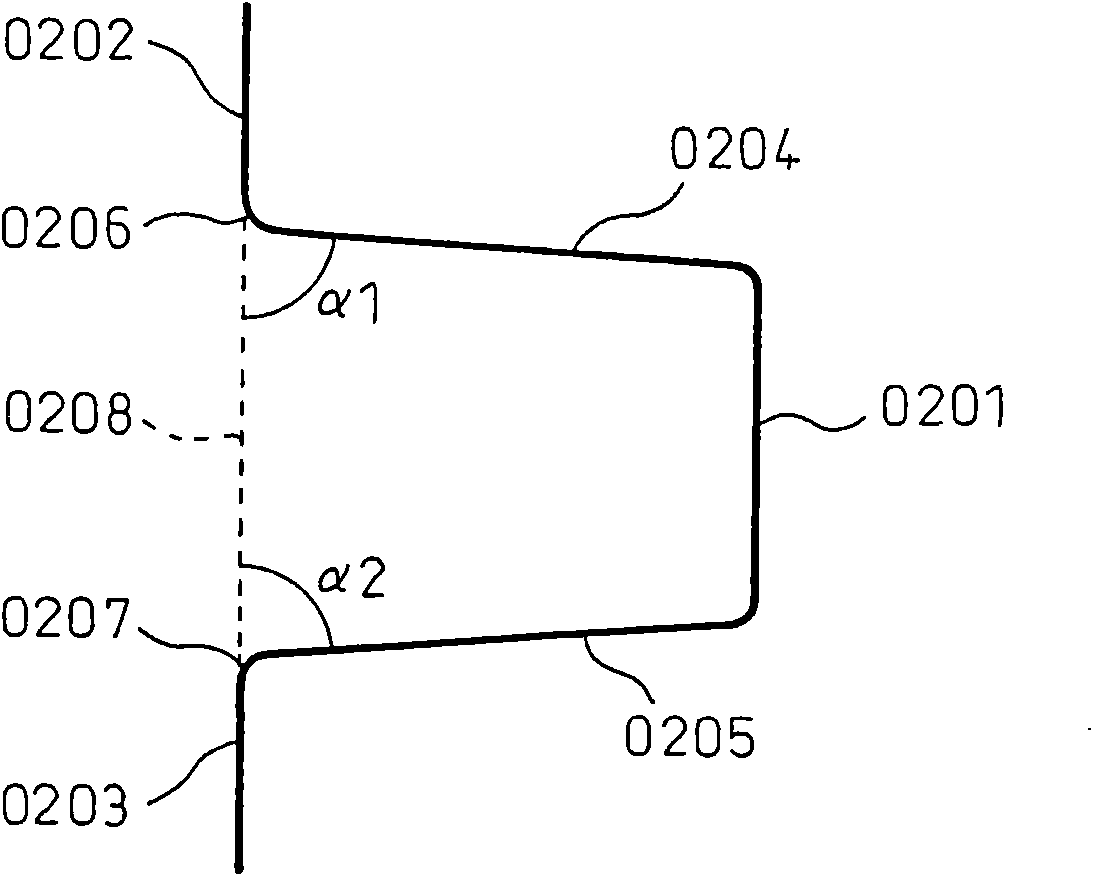
[0170] Relative to the horizontal plane, from the upper web and the lower web are 5 (degrees), ie α 1 : 85 (degrees), α 2 : 85 (degrees),

[0171] Rib width 25(mm), rib spacing (L) 50(mm),

[0172] Rib ...

Embodiment 3

[0176] Hereinafter, the present invention will be specifically described using examples.

[0177]As the metal absorber of Example 3(a) of the present invention, a test body was formed with the following materials, working methods, and shapes.

[0178] Material: A thin steel plate with a tensile strength of 440 (MPa) and a plate thickness of 0.7 (mm) is used.

[0179] Forming: using Figure 15 The die shown is formed by stamping as Figure 22 Approximate hat shape shown in (a).

[0180] Shape: upper and lower dimensions (the maximum width of the upper web and lower web) 45 (mm),

[0181] Front-to-back dimensions (the front-to-back length of the upper web and the lower web) 50 (mm),

[0182] Right and left dimensions (car width direction length) 500 (mm),

[0183] The length (one side) of the upper flange and the lower flange is 20 (mm),

[0184] The length from the bent part in the middle of the upper flange and the lower flange to the central flange is 25 (mm),

[0185]...


PUM


Abstract

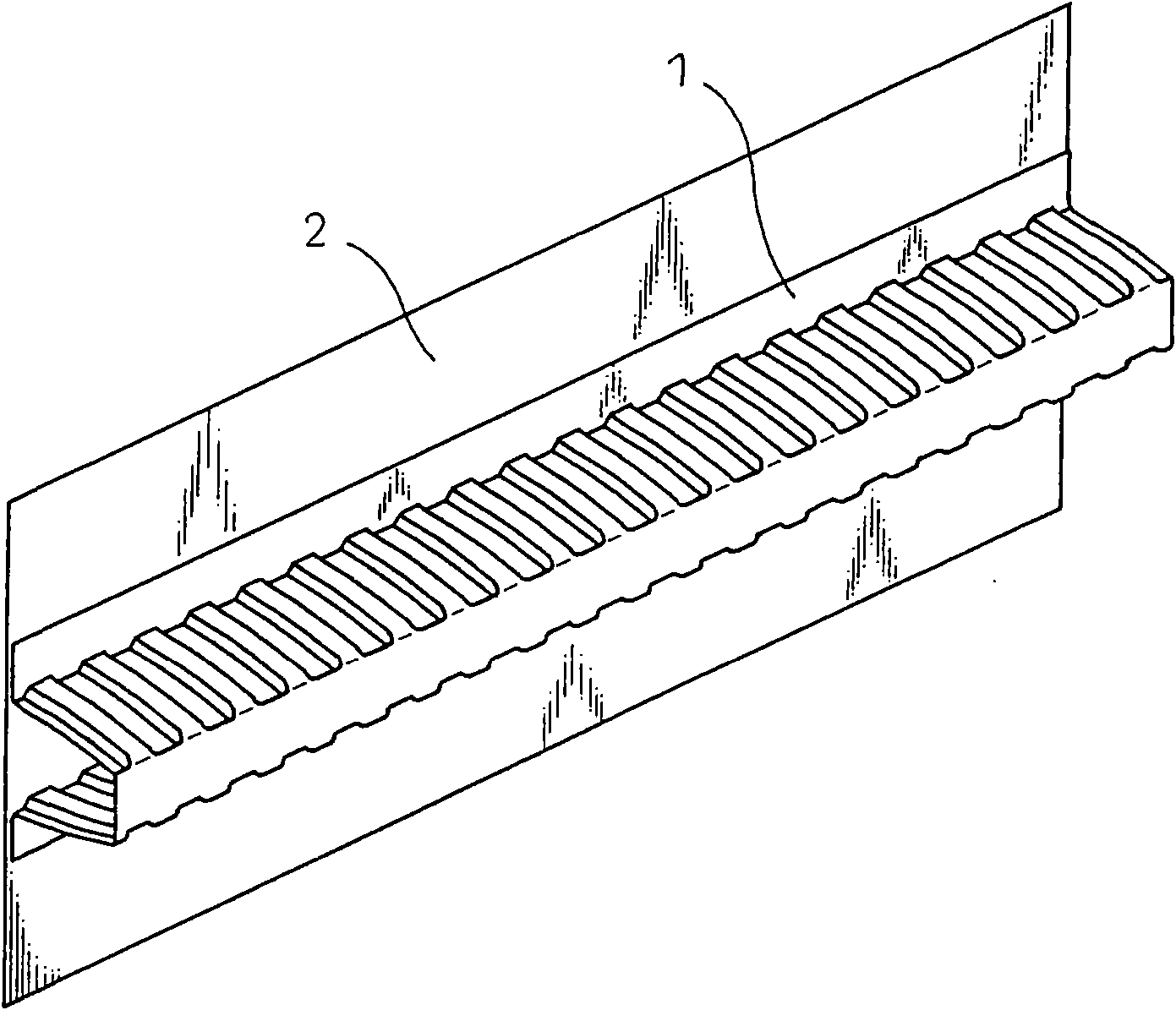
A vehicular metal absorber which efficiently absorbs the impact energy exerted from pedestrian legs at a short stroke and protects the pedestrian legs with less remaining crushed parts in the event ofcollision between pedestrian and automobile. The vehicular metal absorber comprises a center flange, a top web and a bottom web leading to both sides of the center flange, a top flange leading to thetop web and a bottom flange leading to the bottom web as a lengthy absorber with its cross-sectional surface integrally formed in a hat shape. On the hat-shaped cross-sectional surface, the inner angle a1 formed between the top web and a flange surface including the top flange and bottom flange as well as the inner angle a2 formed between the bottom web and the above flange surface is above 0 (degree) and below 90 (degrees), and a concave or convex bead roughly parallel to the anteroposterior direction of a vehicle is provided at either one or both of the top web and bottom web.

Description

technical field [0001] The invention relates to a bumper part, which absorbs the impact energy generated when a car collides with other vehicles and pedestrians, and helps to protect the legs of pedestrians. Background technique [0002] At present, in the laws of each country and region or NCAP (New Car Assessment Program / New Car Safety Evaluation Test), regulations and evaluations related to collisions of automobiles are performed. Among them, in recent years, in addition to pedestrian head protection, research on leg protection has also been carried out (refer to "European Enhanced Vehicle-safety Committee, Improved Test Methods to Evaluate Pedestrian Protection Afforded by Passenger Cars", EEVC Working Group 17 report, December 1998: "European Committee for the Promotion of Vehicle Safety, Improved Test Method for Assessing the Protection of Passenger Cars for Pedestrians", EEVC Working Group No. 17 Report, December 1998), Increasing requirements for leg protection in pe...

Claims


Application Information

Patent Timeline
Patent Type & Authority Applications(China)
IPC IPC(8): B60R19/18B60R19/04
CPCB60R21/34B60R2019/1826B60R19/18B60R2019/186B60R19/04B60R19/34
Inventor 野岛耕司萨川勋有贺高上西朗弘丹羽俊之
Owner UNIPRES CORP
Learn More