

Device and method for testing thermal cycling performance of thermal barrel coating
A technology of thermal barrier coating and testing device, applied in the field of TBC, which can solve problems such as human interference, heavy workload, and inability to perform accurate evaluation
Active Publication Date: 2010-02-10
CHINESE ACAD OF AGRI MECHANIZATION SCI
View PDF0 Cites 44 Cited by
- Summary
- Abstract
- Description
- Claims
- Application Information
AI Technical Summary
Problems solved by technology
[0006] The above-mentioned thermal shock test needs to be manually operated, the workload is heavy, the test conditions are not uniform, and the interference of human factors is serious
Some important test parameters, such as the heating and cooling rate of the sample, the thermal shock morphology change of the sample, and the formation and expansion of thermal cracks, etc. cannot be observed, recorded and saved in time, and such test results can only be used for thermal bar
Method used
View moreImage
Smart ImageViewing Examples

Examples
 PUM
 Abstract
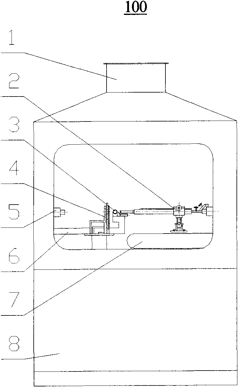
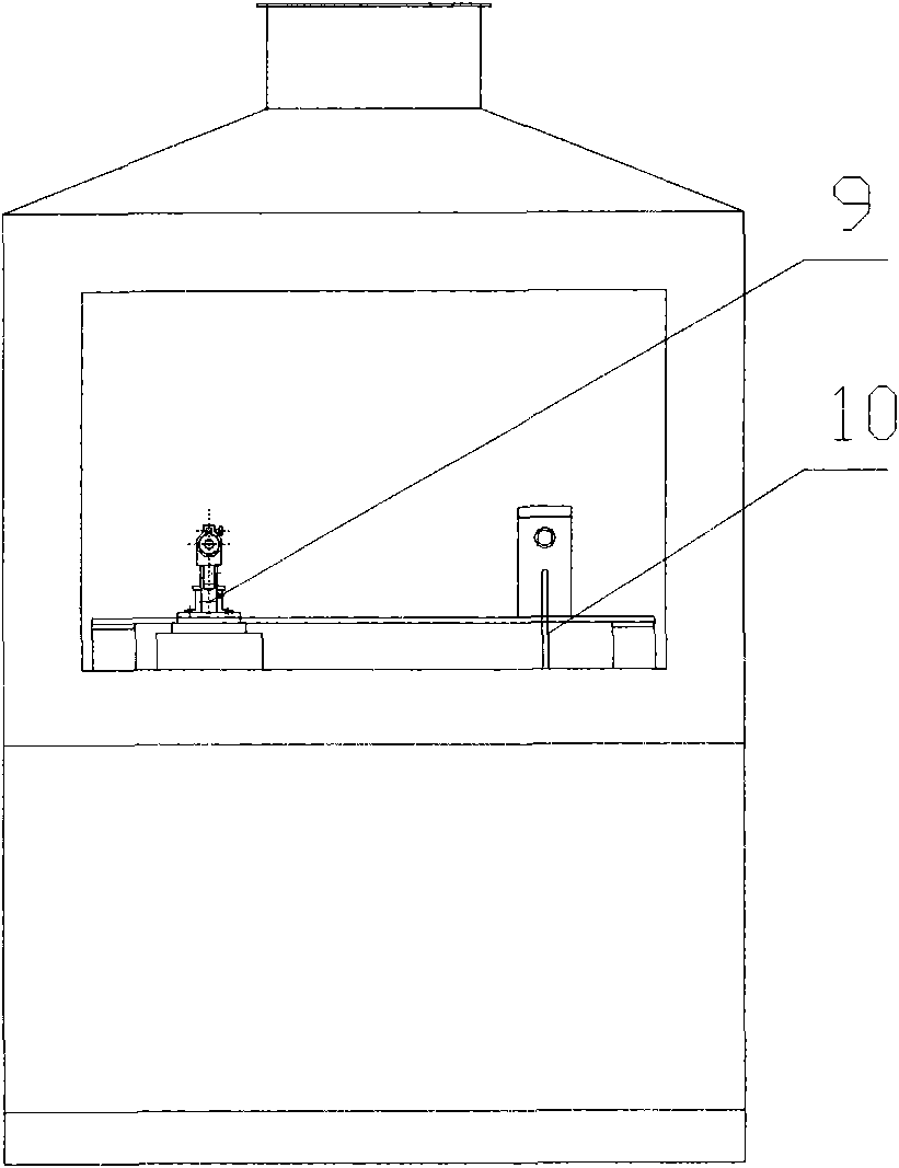
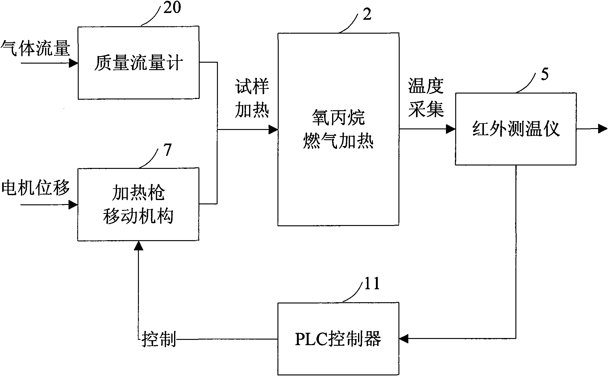
The invention discloses a device and a method for testing the thermal cycling performance of a thermal barrel coating. The device is arranged in a case and comprises a sample base for assembling a sample, a temperature measuring meter which is arranged in the case, a sample cooling device and a control system, a heating gun bracket, a heating gun, an automatic ignition device and a heating gun moving device. According to the control of the control system, after the sample is assembled on the sample base, the automatic ignition device is started to automatically ignite, and the heating gun moving device moves the heating gun to a place in certain distance from the sample to heat the sample; when the temperature measuring meter measures that the temperature of the sample reaches holding time, heating is automatically stopped, and the sample cooling device is started to cool the sample; when the sample is cooled to a temperature required by the test, the sample cooling device is closed; and the automatic ignition device automatically ignite again to start the next working cycle until the thermal barrel coating is stripped off and then the test is ended. The device and the method realize the test of the thermal cycling performance of the thermal barrel coating.
Description
technical field [0001] The invention relates to TBC (Thermal Barrier Coating, thermal barrier coating) technology, in particular to a thermal cycle performance test device and a test method thereof for dynamic simulation of thermal barrier coatings on hot-end parts of aero-engines. Background technique [0002] The behavior of thermal barrier coatings under actual working conditions is a very complex product of the combined effects of multiple factors. The physical properties of materials often cannot directly reflect the real behavior of thermal barrier coatings under working conditions. [0003] At present, the evaluation of thermal barrier coating performance in domestic and foreign literature is mostly limited to the test results of static room temperature tests. The measured physical and chemical test indicators include thermal conductivity, microhardness, specific heat capacity, bonding strength, etc., which cannot truly reflect the hot end of the aeroengine. The cond...
Claims
Login to View More Application Information
Patent Timeline
 IPC IPC(8): G01N3/60G01J5/60
Inventor张天剑汪瑞军程家龙方涛王伟平
OwnerCHINESE ACAD OF AGRI MECHANIZATION SCI