Ultrasonic testing system of dual robot arms and method thereof

a technology of ultrasonic testing and robot arms, which is applied in the direction of process control, machine control, process control, etc., can solve the problems of low test efficiency and high testing cost of composite materials workpieces, insufficient space for movement stops of robot arms, and method cannot test the surface quality of semi-closed workpieces with a narrow internal spa

Pending Publication Date: 2021-10-21
BEIJING INSTITUTE OF TECHNOLOGYGY
View PDF0 Cites 0 Cited by
  • Summary
  • Abstract
  • Description
  • Claims
  • Application Information

AI Technical Summary

Benefits of technology

[0007]As a result, by providing an extension rod connected with the emitting probe or the receiving probe at the tail-end of at least one of the robot arms, it is possible to extend into the interior of the workpiece for testing quality of the interior and surface of the workpiece. And by providing an extension rod rotating shaft between the extension rod and the probe, it is possible to adjust the probe so that it is perpendicular to the surface of the workpiece, thereby receiving ultrasonic signals in a more effective way.
[0012]As a result, by providing the extension rod between the master robot arm and the emitting probe and / or between the slave robot arm and the receiving probe, it helps the probe(s) to extend into the semi-closed workpiece with a narrow internal space so as to test the quality of the surface and interior of the workpiece. And by providing the extension rod rotating shaft between the extension rod and the emitting probe or / and between the extension rod and the receiving probe, it is possible to control the rotation of the extension rod rotating shaft automatically or via the robot arm controllers, so that the receiving probe and the emitting probe keep perpendicular to the surface of the workpiece, thereby ensuring the emitting and receiving efficiency of the ultrasonic signals.
[0020]As a result, by providing the extension rod, it helps the probe(s) to extend into the semi-closed workpiece with a narrow internal space so as to test the quality of surface and interior of the workpiece. And by providing the extension rod rotating shaft, it is possible to adjust the receiving probe and the emitting probe so that they are kept perpendicular to the surface of the workpiece, thereby improving the reliability of testing results. By using the X-axis constraint method, the X-axis of each of the auxiliary coordinate systems is corrected so that it is in the tangent direction of the trajectory, that is the extension rod is kept parallel to the central axis of the workpiece, thereby avoiding collision between the robot arm and the workpiece. In addition, by converting the posture data in the trajectory data into Euler angles, the trajectory data is thus readable to the controllers of the master and slave robot arms so that the robot arms with the probes can be controlled based on the trajectory data to perform a full-coverage quality test.
[0027]As a result, the Euler angles of the coordinate system of workpiece can be obtain by equal relationship between the Euler angles transformation matrix and the rotation matrix, and then the Euler angles of the coordinate system of workpiece can be converted into the Euler angles of the base coordinate systems of master and slave robot arms readable to the controllers of the master and slave robot arms by the transformation relationships among the coordinate system of workpiece and the base coordinate systems of master and slave robot arms. Therefore, it is possible to control the movement of the robot arms according to the trajectory generated by the CAM software for a quality testing of the workpiece.

Problems solved by technology

The superior performance of composite materials undoubtedly provides a good opportunity for applying new technologies, new materials and optimizing the engine performance in this field, but the workpieces made by the composite materials have low testing efficiency and high testing cost.
However, for those semi-closed workpieces with narrow internal spaces, insufficient space for movement stops the robot arms for expanding into the interior of the workpiece to perform an ultrasonic transmission test.
Therefore, this method cannot test the surface quality of semi-closed workpieces with a narrow internal space such as a cylinder.

Method used


Image

  • Ultrasonic testing system of dual robot arms and method thereof
  • Ultrasonic testing system of dual robot arms and method thereof
  • Ultrasonic testing system of dual robot arms and method thereof

Examples


Embodiment Construction

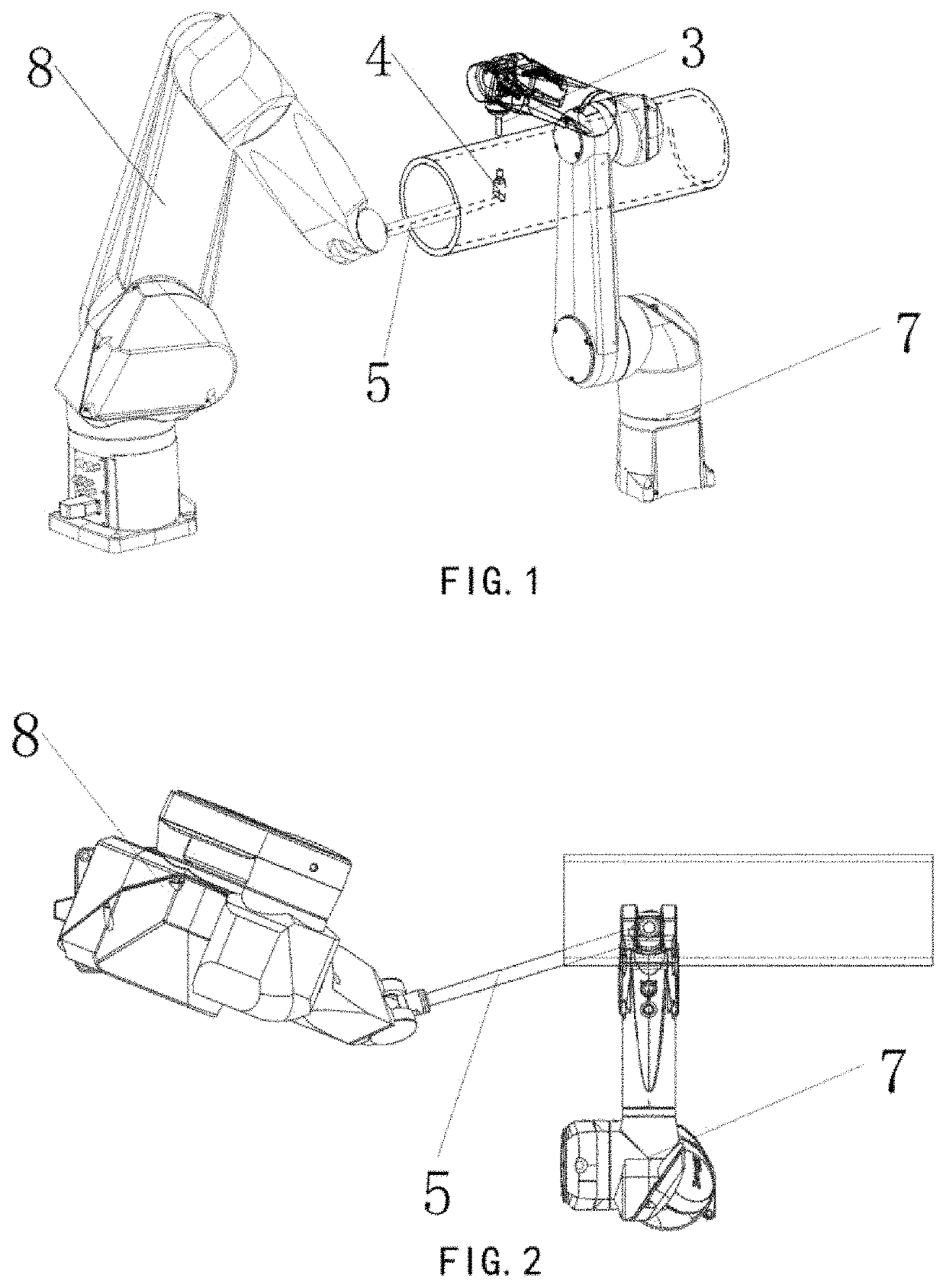
[0036]In order to solve the problem that a receiving probe or an emitting probe cannot reach into a workpiece to perform testing, a robot arm may be equipped with an extension rod as a tool to extend into the internal space of the workpiece and perform testing. However, the robot arm with six degrees of freedom may collide with the workpiece due to enter-constraint or improper constraint of postures. As shown in FIG. 1 and FIG. 2, a robot arm 8 is equipped with an extension rod 5 on which an emitting probe 4 is installed, and a robot arm 7 is equipped with a receiving probe 3 at its tail-end, wherein the extension rod 5 collides with the tested workpiece and causes a testing accident. Therefore, it is necessary to propose a new testing method to solve the problem of collision between the probe and the workpiece.

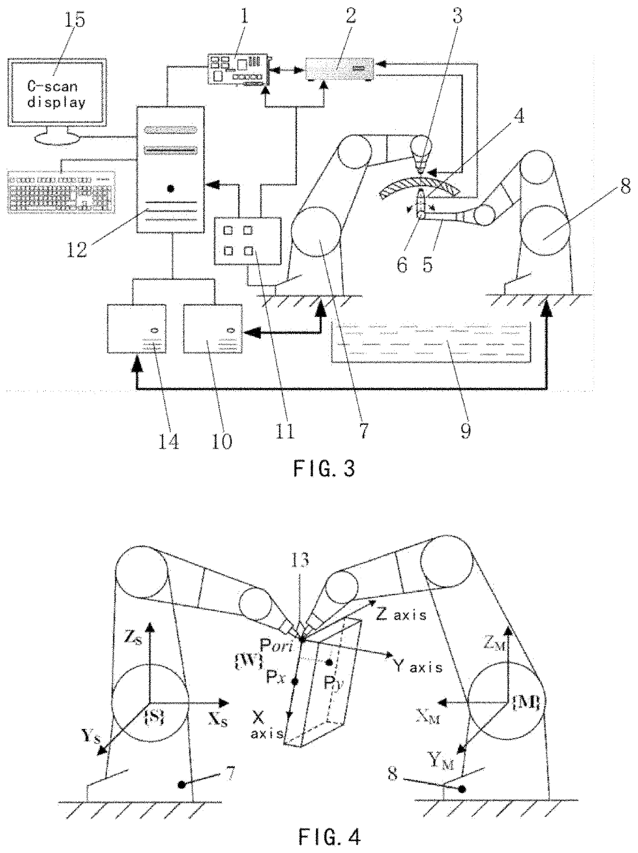
[0037]FIG. 3 shows an ultrasonic testing system of dual robot arms with an extension rod. The ultrasonic testing system includes an ultrasonic acquisition card 1 configured f...


PUM

PropertyMeasurementUnit
ultrasonic testingaaaaaaaaaa
lengthaaaaaaaaaa
ultrasonicaaaaaaaaaa

Abstract

An ultrasonic testing system of dual robot arms and an ultrasonic testing method for use in testing quality of surface and interior of a workpiece. The system includes an extension rod provided between a tail-end of a master robot arm and an emitting probe and / or between a tail-end of a slave robot arm and a receiving probe. One or more connected extension rod rotating shafts is provided between the extension rod and the emitting probe or between the extension rod and the receiving probe. The method uses an X-axis constraint method to convert posture data of the discrete points in a trajectory file of the tested workpiece into Euler angles, and constrain the X-axes of the auxiliary coordinate systems at the same time so that the positive direction of the X-axis of each of the auxiliary coordinate systems is the trajectory tangent direction.

Description

CROSS-REFERENCE TO RELATED APPLICATIONS[0001]This application is a National Stage application of International Application No. PCT / CN2019 / 096113 filed on Jul. 16, 2019 which claims priority to Chinese Patent Application Serial No. CN 201810779181.0 filed Mar. 15, 2018.BACKGROUNDField[0002]The present disclosure belongs to the technical field of non-destructive ultrasonic testing, and in particular to an ultrasonic testing system of dual robot arms and method thereof.Discussion of the Related Art[0003]With the development of materials science and technology, the use of composite materials to replace metal materials for manufacturing a variety of workpieces has increased, especially the workpieces with complex curved surfaces in the aerospace field, as the composite materials has advantages of high stiffness to weight ratio, light weight, good corrosion resistance and fatigue resistance. The superior performance of composite materials undoubtedly provides a good opportunity for applyi...

Claims


Application Information

Patent Timeline
Patent Type & Authority Applications(United States)
IPC IPC(8): B25J9/16G01N29/04G01N29/265B25J9/00
CPCB25J9/1692G01N29/04G01N29/28B25J9/0087G01N2291/0289G01N29/265G01N29/275G01N2291/023B25J9/1682G01N2291/102G01N2291/044G01N2291/045G01N29/225G01N29/041G01N29/043G05B2219/39109G01N2291/2698
Inventor XU, CHUNGUANGGUO, CANZHIHAO, JUANYANG, WANXINXU, XIANCHUNJIA, RUILIZHENG, XINHAO
Owner BEIJING INSTITUTE OF TECHNOLOGYGY
Why Eureka
Try Eureka