
Connector and O-shaped ring mounting groove structure for sealing end face

An end-face sealing and connector technology, which is applied in the field of connectors and the O-ring installation groove structure for end-face sealing, achieves the effects of reducing production processes, improving processing technology, and easily ensuring reliability.

Inactive Publication Date: 2012-11-07
CHINA AVIATION OPTICAL-ELECTRICAL TECH CO LTD
View PDF5 Cites 0 Cited by
  • Summary
  • Abstract
  • Description
  • Claims
  • Application Information

AI Technical Summary

Problems solved by technology

[0003] The object of the present invention is to provide an O-ring installation groove structure for a connector and its end face seal, to solve the problem that the O-ring in the prior art needs to be glued and fixed in the installation groove. At the same time, the present invention The purpose is also to provide a connector

Method used


Image

  • Connector and O-shaped ring mounting groove structure for sealing end face
  • Connector and O-shaped ring mounting groove structure for sealing end face

Examples


Embodiment Construction

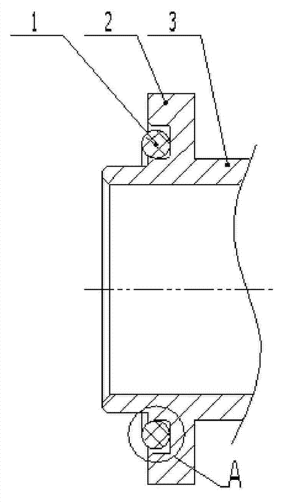
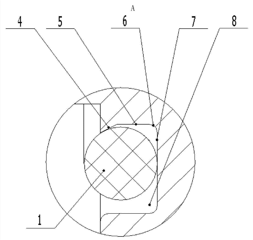
[0016] exist figure 1 , figure 2 Among them, the connector housing 3 is provided with a flange 2, and the sealing end surface of the flange 2 is provided with an O-ring installation groove 8, and the wall surface of the inner groove wall with a smaller diameter of the O-ring installation groove 8 It is composed of a cylindrical surface 5 close to the bottom surface of the groove and a truncated cone surface 4 close to the groove notch. The truncated cone surface 4 is transitionally connected with the cylindrical surface 5 through its small end, and the large end of the truncated cone surface 4 extends to The notch edge of the groove 8 and the truncated cone surface 4 are used to prevent the O-ring 1 from coming out of the O-ring installation groove 8 . The wall surface of the inner and outer groove walls of the O-ring installation groove 8 and the bottom surface 7 are transitioned through the arc surface 6 . The height of the cylindrical surface 5 near the bottom of the inn...


PUM


Abstract

The invention relates to a connector and O-shaped ring mounting groove structure for sealing end face; the wall surface of the inside groove wall with the smaller diameter of the O-shaped ring mounting groove of the connector comprises a column surface close to the groove bottom and a truncated cone surface close to the groove notch; the truncated cone surface is in transitional connection with the column surface through the small end; the large end of the truncated cone surface is extended to the edge of the notch of the groove. The inside groove wall with the smaller diameter of the O-shaped ring mounting groove of the connector is the truncated cone surface at the position close to the groove notch; the truncated cone surface can stop the O-shaped ring mounted in the O-shaped ring mounting groove, thereby preventing the O-shaped ring from separating out, fixing the O-shaped ring without using glue, reducing the working procedure, shortening the production period, and saving the labor force and physical resource.

Description

technical field [0001] The invention relates to a connector and an O-ring mounting groove structure for end face sealing thereof, in particular to a connector for optical and electrical signal transmission and an O-ring mounting groove structure for end face sealing thereof. Background technique [0002] Some connectors used to be installed on the equipment panel are generally fixed on the equipment panel through a flange. For connectors used for optical and electrical signal transmission, a sealing device needs to be provided on the mating surface of the flange and the panel. O-rings are widely used because of their simple structure, good sealing effect and wear compensation. When in use, the O-ring is generally installed in a groove corresponding to its shape. Usually, the wall surface of the inner and outer groove walls of the O-ring installation groove is a cylindrical surface, and the groove bottom surface is a circular ring. In order to prevent the O-ring assemble...

Claims


Application Information

Patent Timeline
Patent Type & Authority Patents(China)
IPC IPC(8): H01R13/52G02B6/36
Inventor 方尚杰
Owner CHINA AVIATION OPTICAL-ELECTRICAL TECH CO LTD
Learn More