Mounting structure of electric box

A technology of installation structure and electrical box, which is applied in the direction of electrical components, etc., can solve the problems of prolonged installation time, not knowing how to disassemble the electrical box, and unsightly appearance, and achieve the effects of simplifying installation, saving cost and time, and wide tolerance range

Inactive Publication Date: 2010-02-10
HAILIN ENERGY TECH
View PDF0 Cites 2 Cited by
  • Summary
  • Abstract
  • Description
  • Claims
  • Application Information

AI Technical Summary

Problems solved by technology

[0016] However, this electrical box fixing method also has obvious defects
First of all, when the electrical box fixed by this fixing method needs to be removed, because the fixing method cannot be observed, the remover often does not know how to remove the electrical box, and the electrical box is often damaged by rough pulling
In addition, after the electrical box is removed from the wall, the installation bottom plate 103 is still fixed on the wall, and it occupies a large area.
Finally, using this fixing method, there are strict requirements on the distance between the hooks 103-2 of the installation base plate 103. When it is necessary to replace another type of electrical box at the same position, it is often necessary to replace the installation base plate 103 together. , resulting in prolonged installation time and waste of materials

Method used


Image

  • Mounting structure of electric box
  • Mounting structure of electric box
  • Mounting structure of electric box

Examples


Embodiment Construction

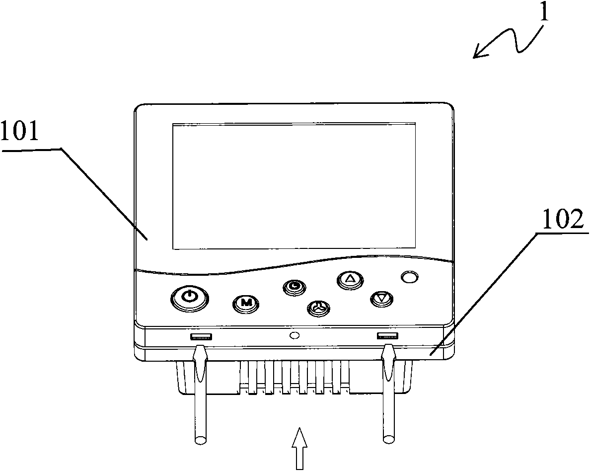
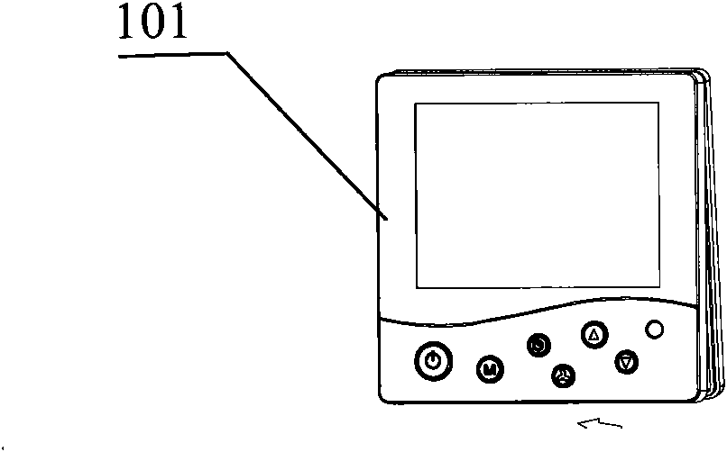
[0040] Please see Image 6 , which shows the installation structure of the electrical box provided by the first embodiment of the present invention. The thick black lines indicate where the mounting structures are connected to each other.

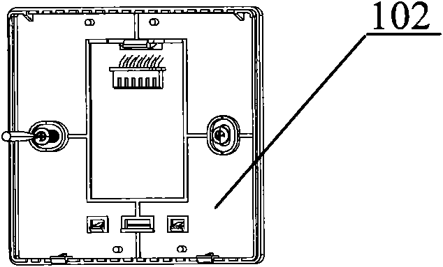
[0041] The structure includes a mounting buckle 2 and a mounting hole 1-1 on the electrical box 1, and a female buckle 3 lined in the mounting hole 1-1.

[0042] Please also see Figure 7 , which shows a perspective view of the installation buckle 2 .

[0043] The mounting buckle 2 is a thin buckle with a certain thickness, and its cross-sectional shape can be square, circular, etc., and generally adopts a circle as shown in the figure. The part near the wall when the mounting buckle 2 is in use is the mounting buckle base plate 2-1. The mounting buckle bottom plate 2-1 is located at the bottom of the mounting buckle 2, and is a thin layer with a cross-sectional diameter slightly larger than the main body part 2-2, and its bottom surfac...


PUM


Abstract

The invention discloses a mounting structure of an electric box. The mounting structure comprises a mounting buckle and a mounting hole on the electric box, wherein the mounting buckle adopts a thin buckle shape with a preset thickness and has a structure by which the mounting buckle can be fixed on the wall surface; the mounting hole is arranged on the bottom surface of the electric box, and a depth matched with the thickness of the mounting buckle and a cross section matched with that of the mounting buckle in shape and size; and a buckling structure is formed between the mounting buckle andthe mounting hole, and the electric box can be directly inserted in the mounting buckle through the mounting hole for fixing. Compared with the prior art, the mounting structure of the electric box can conveniently insert the electric box in the mounting buckle to fix the electric box only by fixing the mounting buckle of which an area is far smaller than that of the mounting bottom plate in theprior art. Because the mounting buckle and the electric box can be directly inserted and matched, the electric box can be detached without detaching the buckle first, and the mounting and demounting actions are simplified.

Description

technical field [0001] The invention provides an installation structure, in particular relates to an installation structure of an electrical box. Background technique [0002] The electrical box refers to the box-shaped object used to place electronic and electrical components inside. The internal circuit is generally used to undertake certain control and detection functions. The external box is mainly to prevent the exposure of electronic and electrical components, provide insulation protection for them, and It can also provide a mounting surface for electrical and electronic components. The multi-speed ceiling fan control box that is often used in daily life is a typical example of an electrical box. [0003] Many electrical boxes need to be mounted on a wall or other surface when in use. The prior art has provided several methods of mounting electrical boxes on walls or other surfaces. [0004] Please see Figure 1 to Figure 3 , the above-mentioned drawings show a comm...

Claims


Application Information

Patent Timeline
Patent Type & Authority Applications(China)
IPC IPC(8): H02G3/10H02G3/08
CPCH02G3/10
Inventor 张志军李海清
Owner HAILIN ENERGY TECH
Why Eureka
Try Eureka