Fuel battery system and power supply control method

A fuel cell system and fuel cell technology, applied in fuel cells, fuel cell additives, solid electrolyte fuel cells, etc., can solve the problems of stopping power generation, freezing of generated water, and inability to start.

Active Publication Date: 2010-02-10
TOYOTA JIDOSHA KK
View PDF2 Cites 11 Cited by
  • Summary
  • Abstract
  • Description
  • Claims
  • Application Information

AI Technical Summary

Problems solved by technology

[0004]However, in the fuel cell system, when starting at a low temperature, if the moisture from the previous system stop remains in the fuel cell, the moisture may f

Method used


Image

  • Fuel battery system and power supply control method
  • Fuel battery system and power supply control method
  • Fuel battery system and power supply control method

Examples


Embodiment approach 1

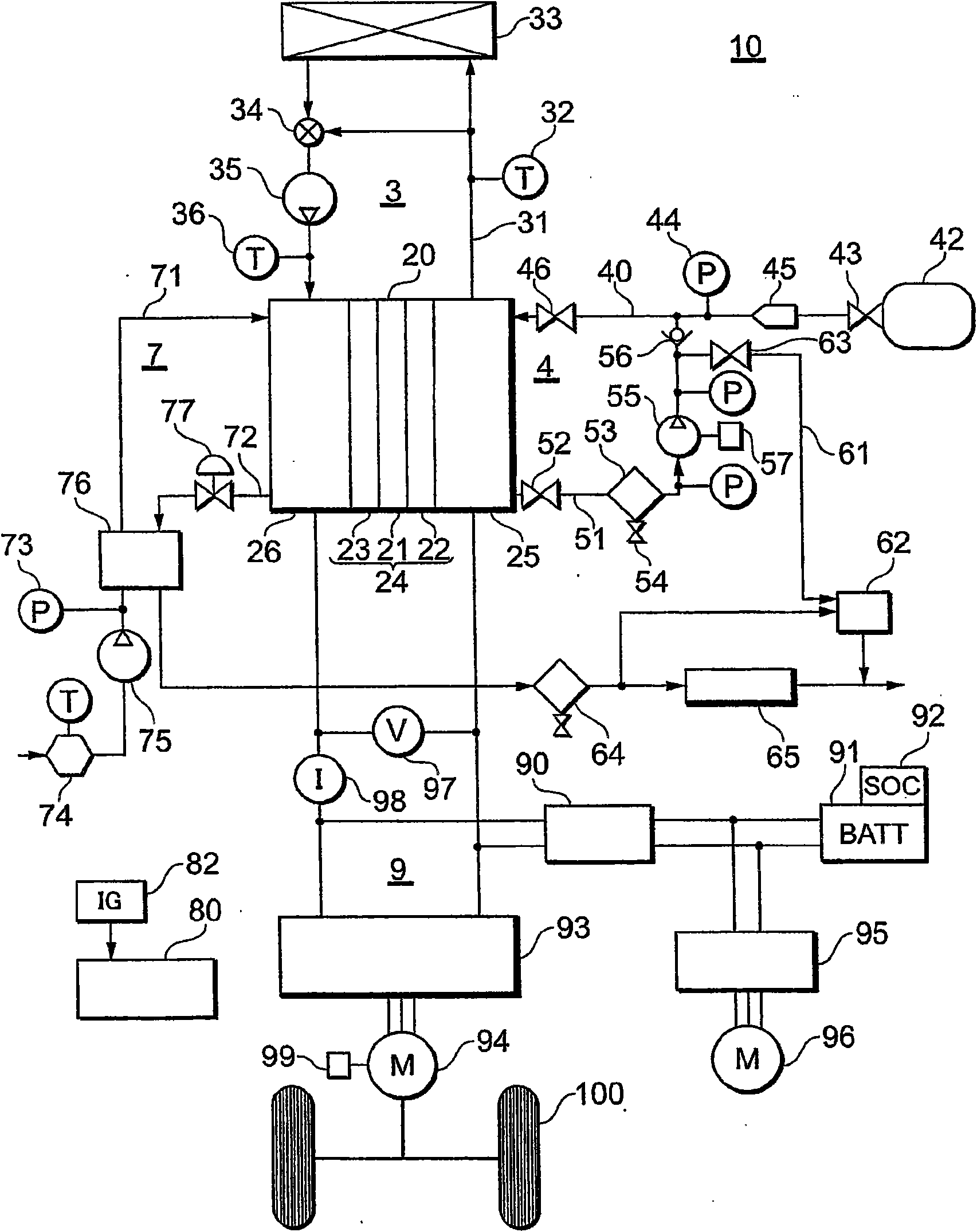
[0061] In Embodiment 1, when estimating the reference voltage of the fuel cell 20 in the air concentration overvoltage target value calculation unit 80b, the temperature sensors 32 and 36 are used as water temperature sensors, and the temperature is estimated from the temperature detected by the water temperature sensors and the command current value. The reference voltage.

[0062] However, as will be described later, it is also possible to estimate the impedance of the fuel cell 20 from the detected current of the current sensor 98 and the detected voltage of the voltage sensor 97, and estimate the reference voltage of the fuel cell 20 from the estimated impedance and the command current value. The reference voltage corresponding to the impedance, that is, the water content.

[0063] In addition, in the air concentration overvoltage target value calculation unit 80b, when estimating the reference voltage of the fuel cell 20, the current of the fuel cell 20 at the end of the ...

Embodiment approach 2

[0077] Next, Embodiment 2 will be described. The second embodiment relates to an example of estimating the air stoichiometry from the impedance of the fuel cell.

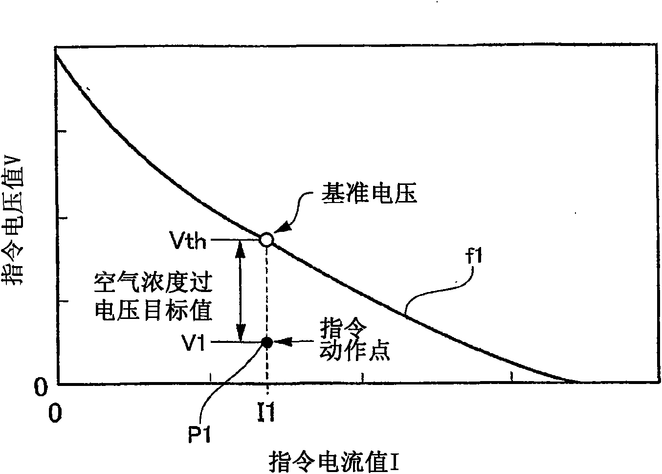
[0078] Figure 7 A graph showing the relationship between reference I-V characteristics and impedance.

[0079] Such as Figure 7 As shown, the reference I-V characteristic changes under the influence of the impedance of the fuel cell as in the case of the temperature of the fuel cell described above. The impedance of the fuel cell corresponds to the amount of water remaining in the cells of the fuel cell, that is, the water content of the fuel cell.

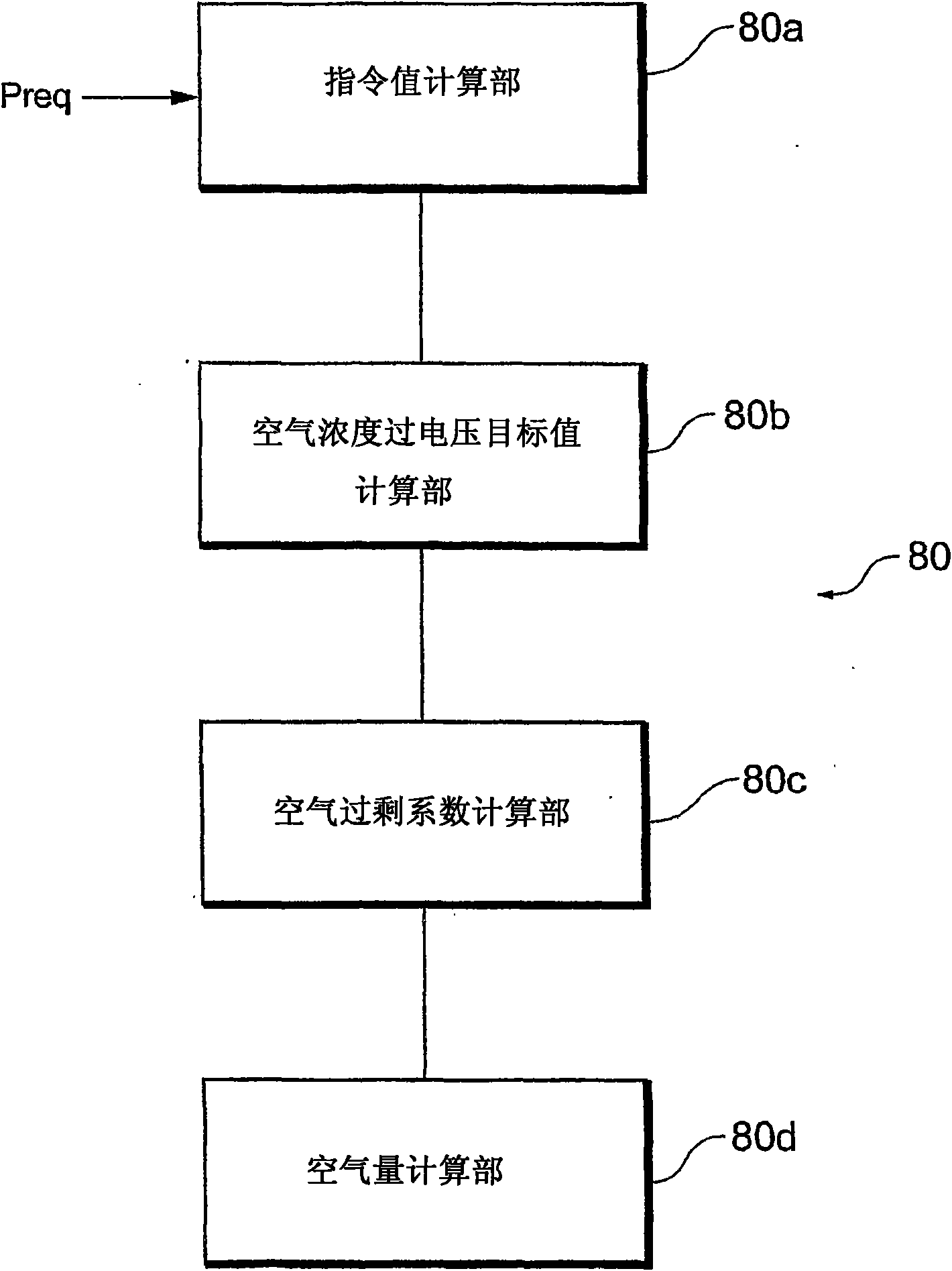
[0080] In Embodiment 2, the air concentration overvoltage target value calculation unit 80b of the control unit 80 preliminarily sets Figure 7 The relationships shown are stored as one-dimensional maps. Furthermore, the air concentration overvoltage target value calculation unit 80b measures the AC impedance of the fuel cell 20 based on the voltage and current o...


PUM


Abstract

The air stoichiometric ratio is determined without using any multi-dimensional map. A fuel battery system computes a command current value and a command voltage value of a fuel battery (20) during low-efficiency power generation according to a requested electric power, estimates a reference voltage of the fuel battery (20) on the basis of the command voltage value and the water temperature when the system uses the command current value as a reference current, determine the difference between the estimated reference voltage and the command voltage value as an air concentration overvoltage target value, computes the air stoichiometric ratio by using the air concentration overvoltage target value, computes the volume of the air during the low-efficiency power generation by using the air stoichiometric ratio, and control the volume of air supplied to the fuel battery (20) according to the computed volume of air. With this, the reference voltage is estimated on the basis of the command voltage value and the water temperature, the difference between the reference voltage and the command voltage value is determined as an air concentration overvoltage target value, and the air stoichiometric ratio is computed by using the air concentration overvoltage target value, thereby determining the air stoichiometric ratio without using any multi-dimensional map.

Description

technical field [0001] The present invention relates to a fuel cell system including a fuel cell that generates electric energy by utilizing an electrochemical reaction of hydrogen and oxygen, and particularly relates to air volume estimation calculation during low-efficiency operation at start-up. Background technique [0002] As a fuel cell that generates electricity by utilizing an electrochemical reaction of hydrogen and oxygen, there is, for example, a solid polymer fuel cell. This solid polymer fuel cell includes a stack formed by stacking a plurality of single cells. The single cells constituting the group have an anode (fuel electrode) and a cathode (air electrode), and a solid polymer electrolyte membrane having a sulfonic acid group as an ion exchange group is interposed between the anode and the cathode. [0003] A fuel gas containing fuel gas (hydrogen gas or modified hydrogen obtained by reforming hydrocarbons to become rich in hydrogen) is supplied to the anod...

Claims


Application Information

Patent Timeline
IPC IPC(8): H01M8/04H01M8/10
CPCH01M8/04089H01M8/04365Y02E60/50H01M8/04395H01M8/04753H01M8/04358H01M8/04649H01M8/04231H01M8/04492H01M8/04992H01M8/04873H01M8/04902H01M8/04865H01M8/04G01R31/36G01R27/00
Inventor 长沼良明
Owner TOYOTA JIDOSHA KK
Why Eureka
Try Eureka