Electric connector

A technology of electrical connectors and stoppers, applied in the direction of connections, electrical components, parts of connecting devices, etc., can solve problems such as inability to obtain space, and achieve the effect of improving retention

Active Publication Date: 2010-02-10
TYCO ELECTRONICS JAPAN GK
View PDF1 Cites 2 Cited by
  • Summary
  • Abstract
  • Description
  • Claims
  • Application Information

AI Technical Summary

Problems solved by technology

However, if the housing 110 is miniaturized and the gap between the corresponding terminal insertion openings 131 adjacent to each other becomes smaller in the front of the housing 110, a space for forming the lock member forming hole 114a from the front of the housing 110 may not be obtained sometimes.

Method used


Image

  • Electric connector
  • Electric connector
  • Electric connector

Examples


Embodiment Construction

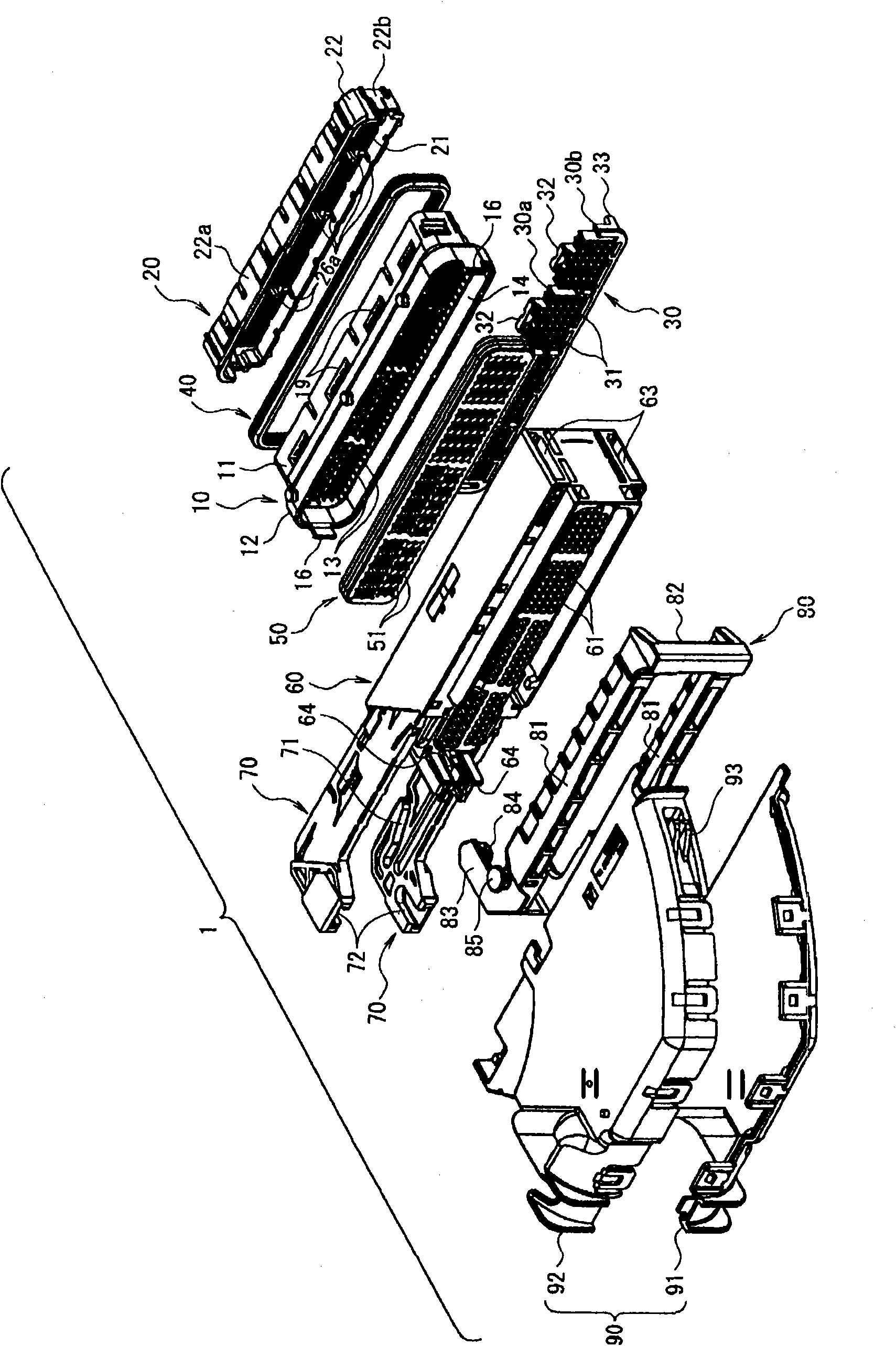
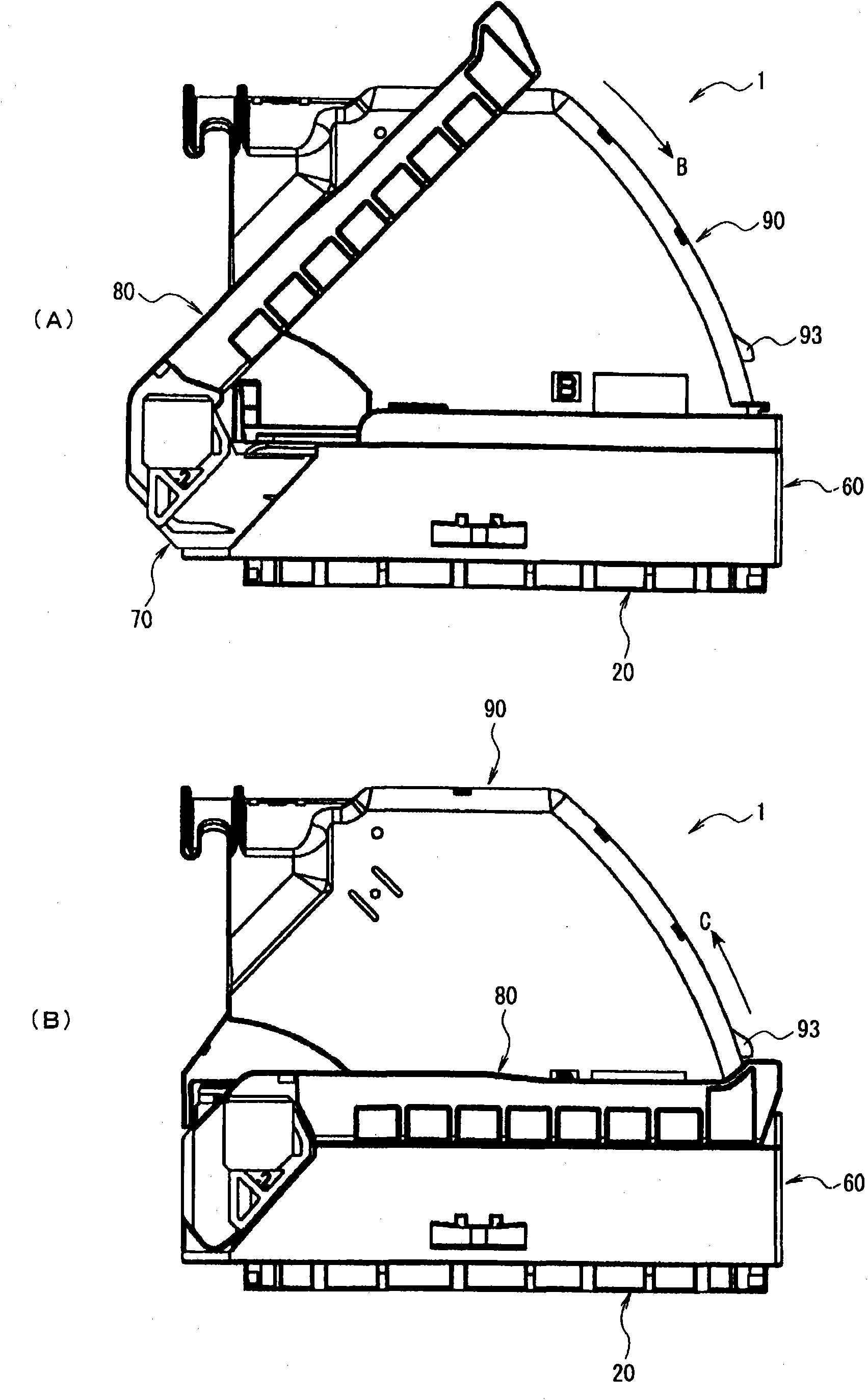
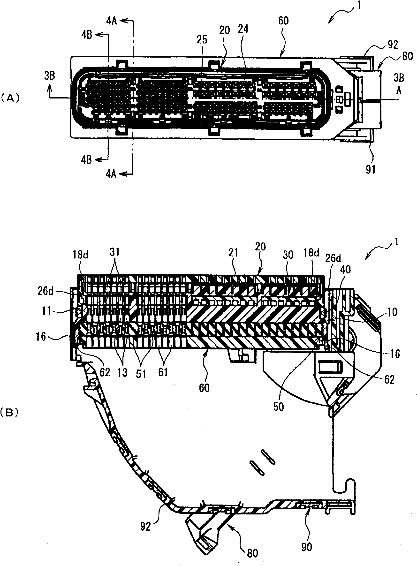
[0048] Next, embodiments of the present invention will be described with reference to the drawings. figure 1 It is an exploded perspective view of the electrical connector of the present invention. figure 2 show figure 1 (A) shows the state of the corresponding connector before mating, and (B) shows the state of the corresponding connector after mating. image 3 show figure 1 (A) is a front view, and (B) is a cross-sectional view along line 3B-3B of (A). Figure 4 show figure 1 The electrical connector, (A) is along the image 3 (A) is a cross-sectional view of line 4A-4A, (B) is along image 3 (A) Cross-sectional view of line 4B-4B.

[0049] figure 1 The illustrated electrical connector 1 is called a so-called lever connector, and includes an inner case (the case in claim 1) 10, a front cover 20, a stopper 30, a first sealing member 40, a second sealing member 50 , housing 60 , a pair of slides 70 , rod 80 and wire cover 90 .

[0050] Figure 5 The inner shell...


PUM


Abstract

There is provided an electrical connector in which the retaining force of retaining a front cover is improved. Electrical connectors 1, and 1' each have a housing 10 having contact accommodating cavities 13; a front cover 20 that is attached to the front side of the housing 10 and that has mating connector inserting openings 24 at positions that correspond to the contact accommodating cavities 13;and a retainer 30 that is attached form the lower side of the housing 10 and that locks contacts accommodated in the contact accommodating cavities 13. Retaining means 27, 28, 32, and 33 is arrangedat the front cover 20 and the retainer 30 to cause the retainer 30 to retain the front cover 20.

Description

technical field [0001] The present invention relates to an electrical connector provided with a shell, a front cover and a stopper, wherein the shell has a contact accommodating cavity, and the front cover is installed on the front side of the shell and forms a corresponding terminal insertion port at a position opposite to the contact accommodating cavity , the stopper is installed from the lower side of the case and stops the contacts accommodated in the contact accommodating chambers. Background technique [0002] It is known from the prior art that there are shells, front covers and stoppers such as Figure 11 with Figure 12 The electrical connector shown (refer to Patent Document 1). Figure 11 It is an exploded perspective view of an example of a conventional electrical connector. Figure 12 is constituted Figure 11 A partial cross-sectional view of the shell of the electrical connector is shown. [0003] Figure 11 The illustrated electrical connector 101 has a ho...

Claims


Application Information

Patent Timeline
Patent Type & Authority Applications(China)
IPC IPC(8): H01R13/42
CPCH01R13/447H01R13/4361H01R13/62977H01R13/62927H01R13/62922
Inventor 小宫山隆一酒卷一诚
Owner TYCO ELECTRONICS JAPAN GK
Why Eureka
Try Eureka