
Continuous composite environmental-friendly filter

A filter and environmental protection technology, applied in the direction of gravity filter, loose filter material filter, filtration and separation, etc., can solve the problems of increasing the adsorption volume of the filter material, shortening the resource use time, speeding up the filter material, etc., to improve the filtration efficiency. Cleaning function, compact and reasonable body structure, and the effect of restoring filtration performance

Inactive Publication Date: 2010-02-17
上海久洁科技有限公司
View PDF5 Cites 6 Cited by
  • Summary
  • Abstract
  • Description
  • Claims
  • Application Information

AI Technical Summary

Problems solved by technology

[0003] However, since the filter materials inside the existing cartridge filter are all designed with a single-layer structure, the suspended solids or particles in the water are all trapped on the surface and inside of the filter material, which increases the adsorption volume of the filter material and reduces the The overall adsorption capacity and efficiency of the filter material; in addition, when cleaning the filter material, because the pollutants are deeply trapped inside the filter layer, the difficulty of cleaning is increased, and the replacement of the filter material is accelerated, which not only shortens the The use time of resources is shortened, and the waste of filter materials is also caused.

Method used


Image

  • Continuous composite environmental-friendly filter
  • Continuous composite environmental-friendly filter

Examples


Embodiment Construction

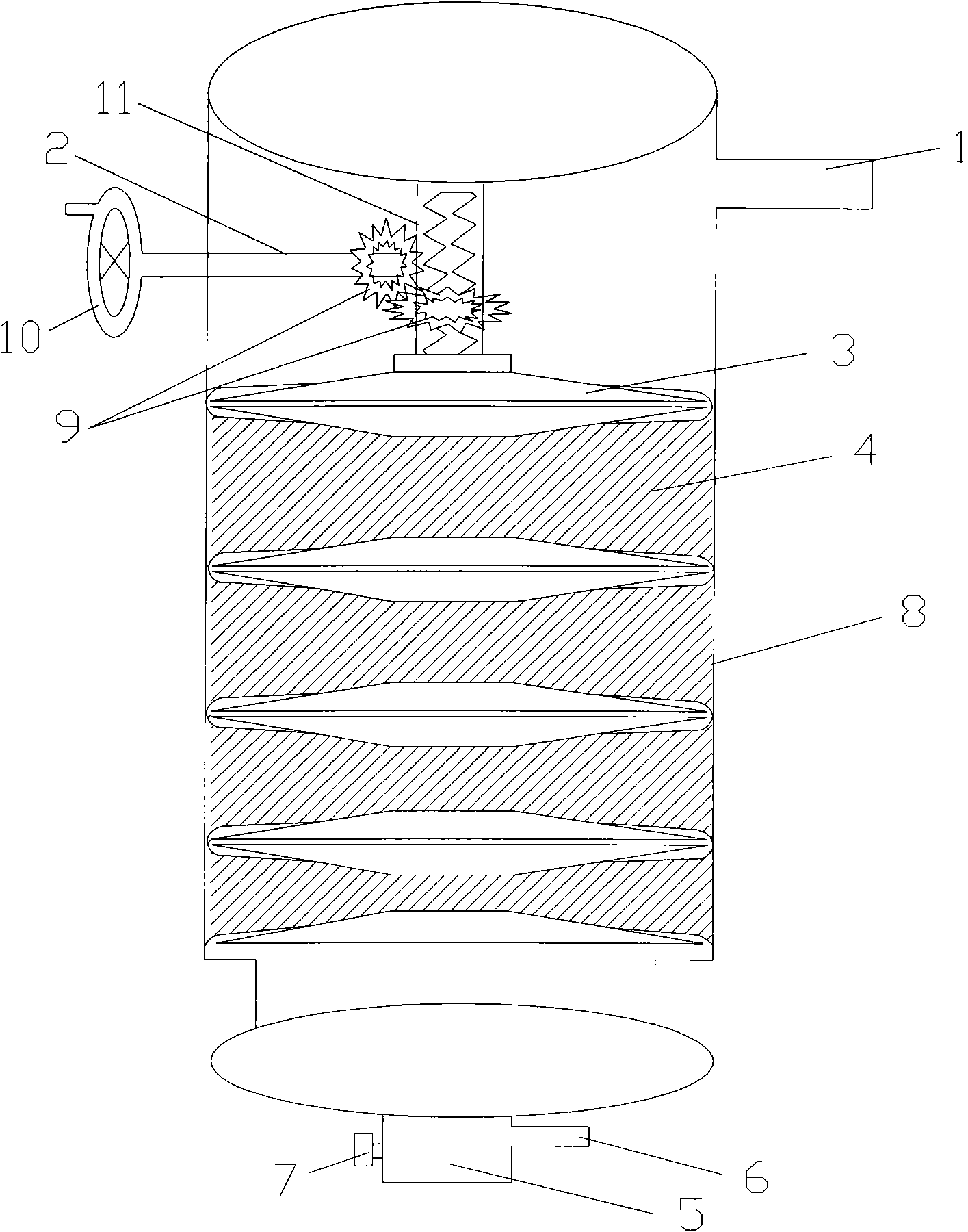
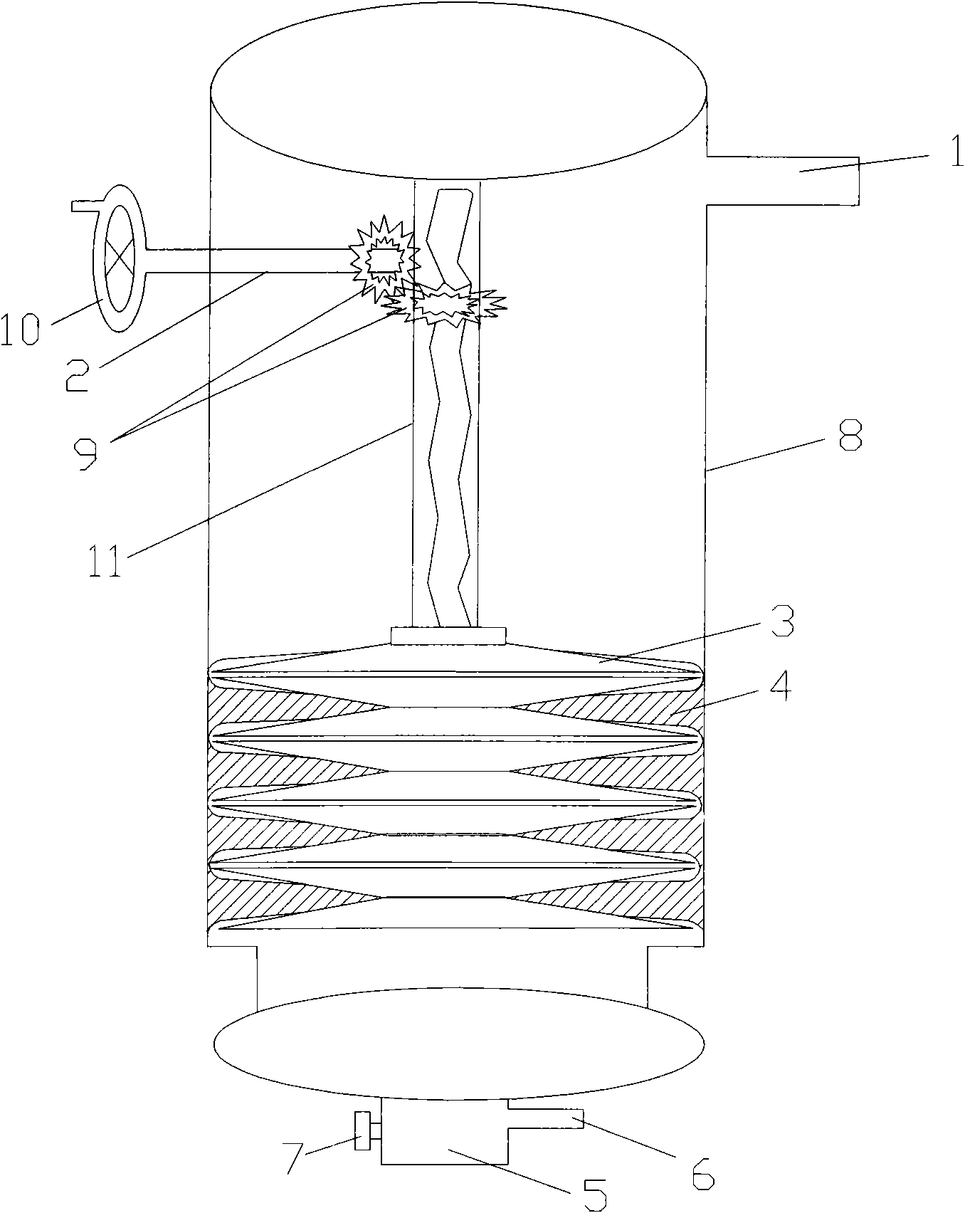
[0024] figure 1 It is a schematic diagram of the internal structure of the present invention, including a filter body 8 , a fiber disc 3 , an environmental protection filter material 4 , an adjustment component 9 , a screw 2 , a manual turntable 10 and a stretching component 11 . The outer surface of the filter main body 8 is provided with a water inlet pipe 1 connected to the filter main body 8, and a density regulator and a fiber disc 3 are arranged inside, and the density regulator is composed of a stretching part 11, an adjusting part 9 and a screw rod 2 , the adjusting part 9 can be constituted by a gear set or a hydraulic part, and the hydraulic part can adjust the stretching part 11 manually or automatically. The gear set is provided with two gears, and the two gears are connected in a vertical and horizontal meshing manner, wherein the vertical gear is connected to one end of the screw 2, and the horizontal gear is arranged on the surface of the tensile member 11 . T...


PUM

PropertyMeasurementUnit
Diameteraaaaaaaaaa
Lengthaaaaaaaaaa

Abstract

The invention relates to a continuous composite environmental-friendly filter. The inside of a main body of the filter is provided with a density regulator and a plurality of fiber plates, wherein theplurality of fiber plates are sequentially and orderly arranged; and a multi-layer environmental-friendly filter material is arranged between the adjacent fiber plates. The environmental-friendly filter material is made from flexible fiber bundles, and has the density divided into a plurality of different layers from top to bottom. The density regulator consists of a regulating part, a stretchingpart and a screw; the screw is connected with a handwheel outside the main body of the filter, and the regulating part can consist of a gear set or an oil pressure component. The regulating part is connected with one end of the screw and the stretching part respectively; and one end of the stretching part is connected with the fiber plates, while the other end is connected with the inner side surface of the main body of the filter. The filter drives the fiber plates to squeeze or release the environmental-friendly filter material through the stretching part so as to control the density of theenvironmental-friendly filter material, not only improves the functions of filtration and cleaning of an organism, but also realizes the effect of deep filtration, and can be widely applied to the continuous filtration of liquids.

Description

technical field [0001] The invention relates to a filter, in particular to a continuous composite environmental protection filter. Background technique [0002] Filtration is the last procedure used to remove suspended solids and colloids in water and wastewater. Filtration devices are widely used in various treatments such as drinking water treatment, domestic drinking water treatment, domestic sewage treatment, industrial wastewater reuse treatment, and advanced wastewater treatment. In process. At present, there are many types of filtration equipment at home and abroad, which can be divided into two categories in terms of types, namely, gravity filtration that flows from top to bottom and upflow filtration that flows from bottom to top. [0003] However, since the filter materials inside the existing cartridge filter are all designed with a single-layer structure, the suspended solids or particles in the water are all trapped on the surface and inside of the filter mater...

Claims


Application Information

Patent Timeline
IPC IPC(8): B01D24/12B01D24/46B01D37/03
Inventor 田心廸
Owner 上海久洁科技有限公司
Learn More