Machining and forming method of compression-resisting leakproof shedding preventing pipeline joint
A pipe joint, processing and forming technology, applied in the direction of pipe/pipe joint/fitting, threaded connection, sleeve/socket connection, etc., can solve the problems of easy cracking and water leakage of pipe joints, and improve the degree of tightness and reliability , Improve production efficiency and improve quality
- Summary
- Abstract
- Description
- Claims
- Application Information
AI Technical Summary
Problems solved by technology
Method used
Image

Examples
Embodiment Construction
[0015] The features of the present invention and other related features will be further described in detail below in conjunction with the accompanying drawings through embodiments, so as to facilitate the understanding of those skilled in the art:
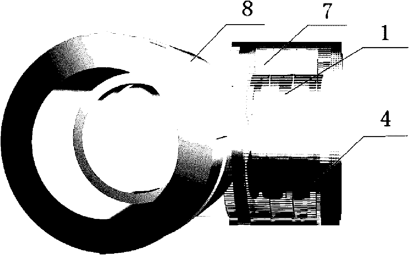
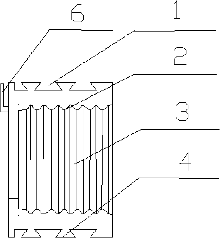
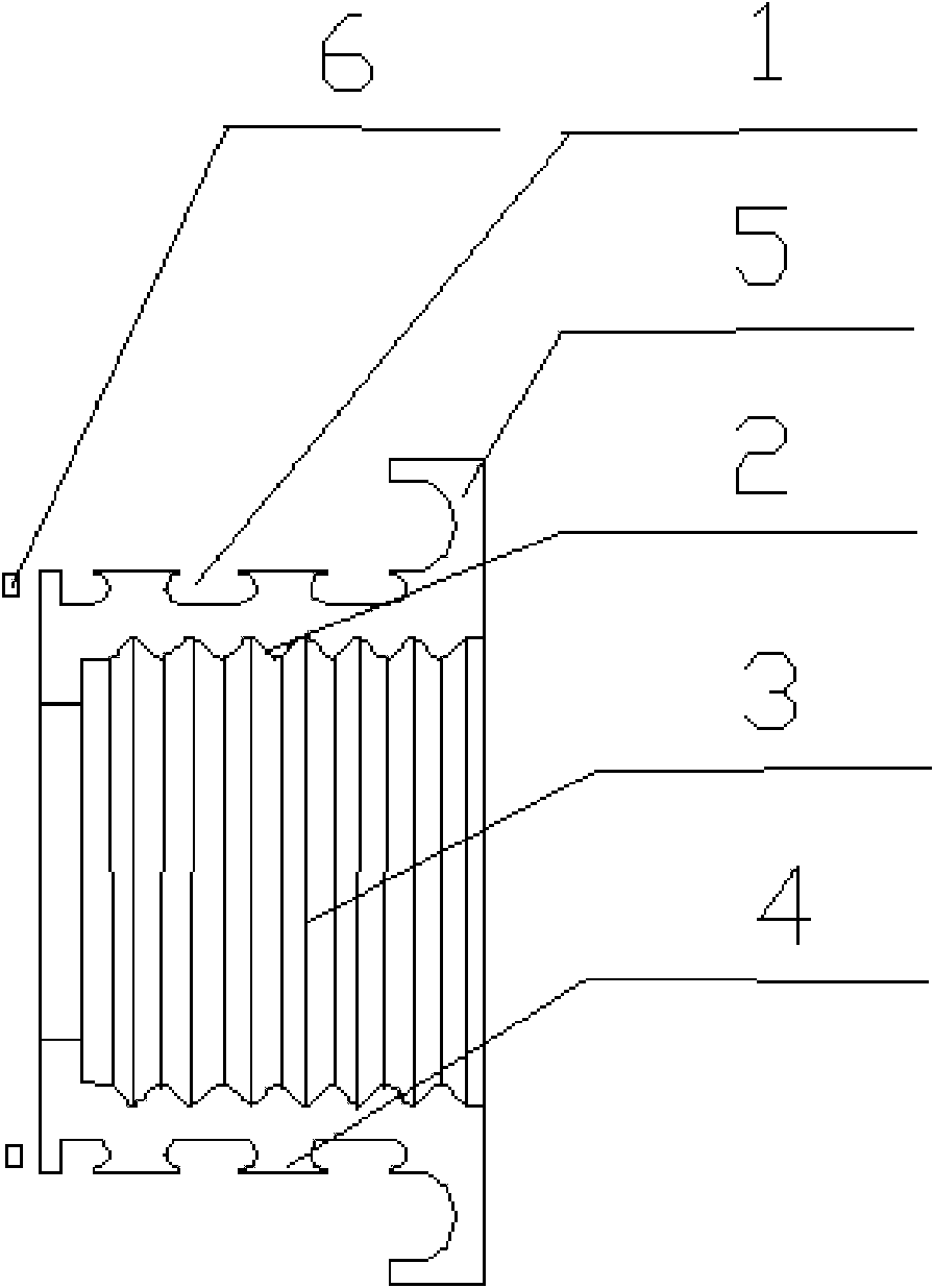
[0016] attached Figure 1-5 The middle marks 1-8 represent the annular slot 1, the internal thread 2, the pipe 3, the outer wall of the pipe 4, the annular boss 5, the fan-shaped slot 6, the injection molding material 7, and the internal thread elbow 8.
[0017] This embodiment takes a pressure-resistant, leak-proof, and fall-off-proof pipe joint processing and forming method for an internally threaded elbow as an example. figure 1 Shown is the schematic diagram of the internal thread elbow shape. from figure 1 It can be seen that the internally threaded elbow 8 is embedded with a metal pipe connector, the outside of the metal pipe connector is combined with the elbow through injection molding to form an integral structure, and t...
PUM
 Abstract
Description
Claims
Application Information
 - R&D
- Intellectual Property
- Life Sciences
- Materials
- Tech Scout
- Unparalleled Data Quality
- Higher Quality Content
- 60% Fewer Hallucinations
Browse by: Latest US Patents, China's latest patents, Technical Efficacy Thesaurus, Application Domain, Technology Topic, Popular Technical Reports.
© 2025 PatSnap. All rights reserved.Legal|Privacy policy|Modern Slavery Act Transparency Statement|Sitemap|About US| Contact US: help@patsnap.com