

System and method for detecting uniformity of pixels of display screen
A detection method and detection system technology, which can be applied in the direction of measuring electricity, measuring devices, measuring electrical variables, etc., and can solve problems such as slow processing speed.
- Summary
- Abstract
- Description
- Claims
- Application Information
AI Technical Summary
Problems solved by technology
Method used
Image

Examples
Embodiment 1
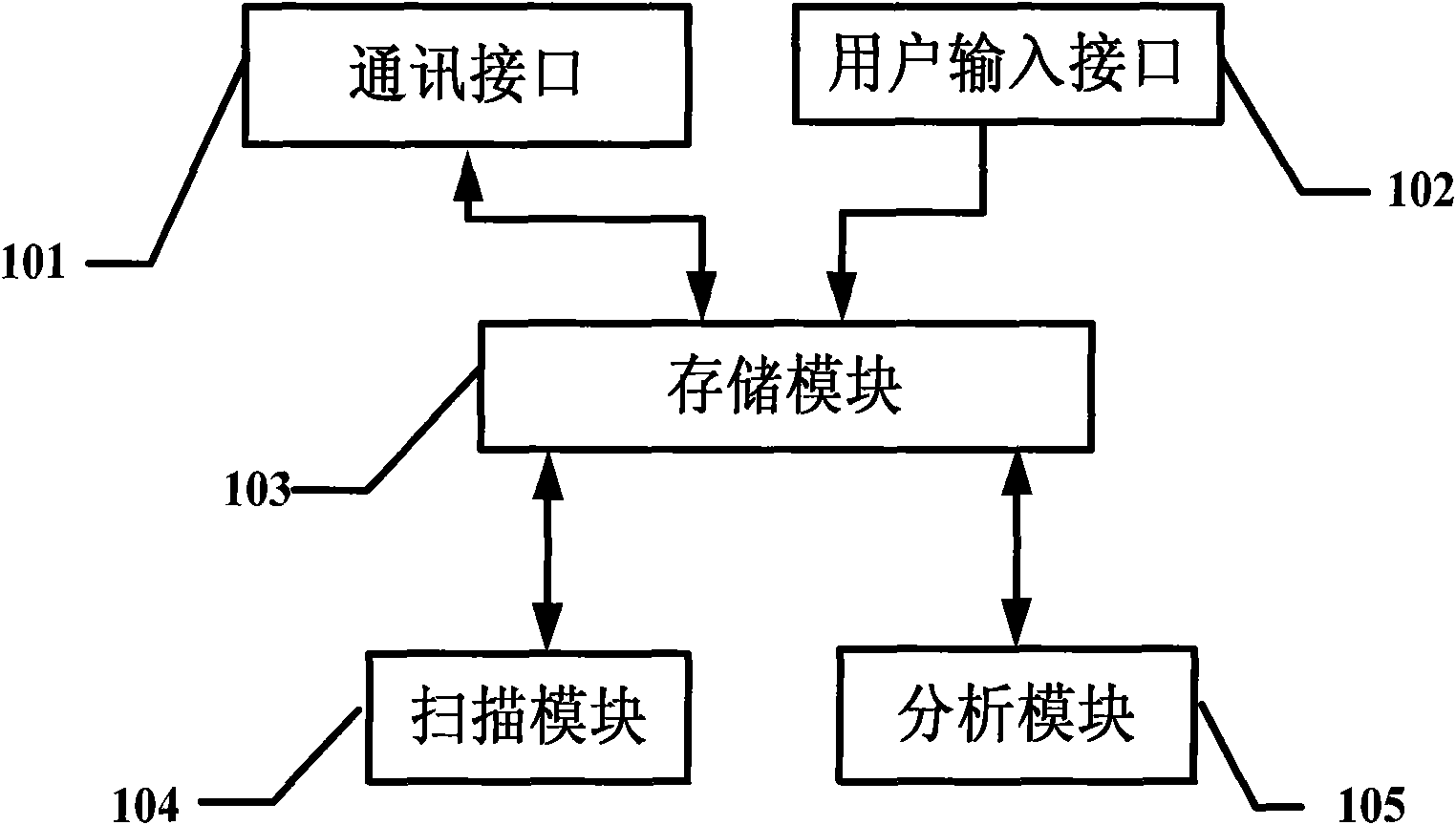
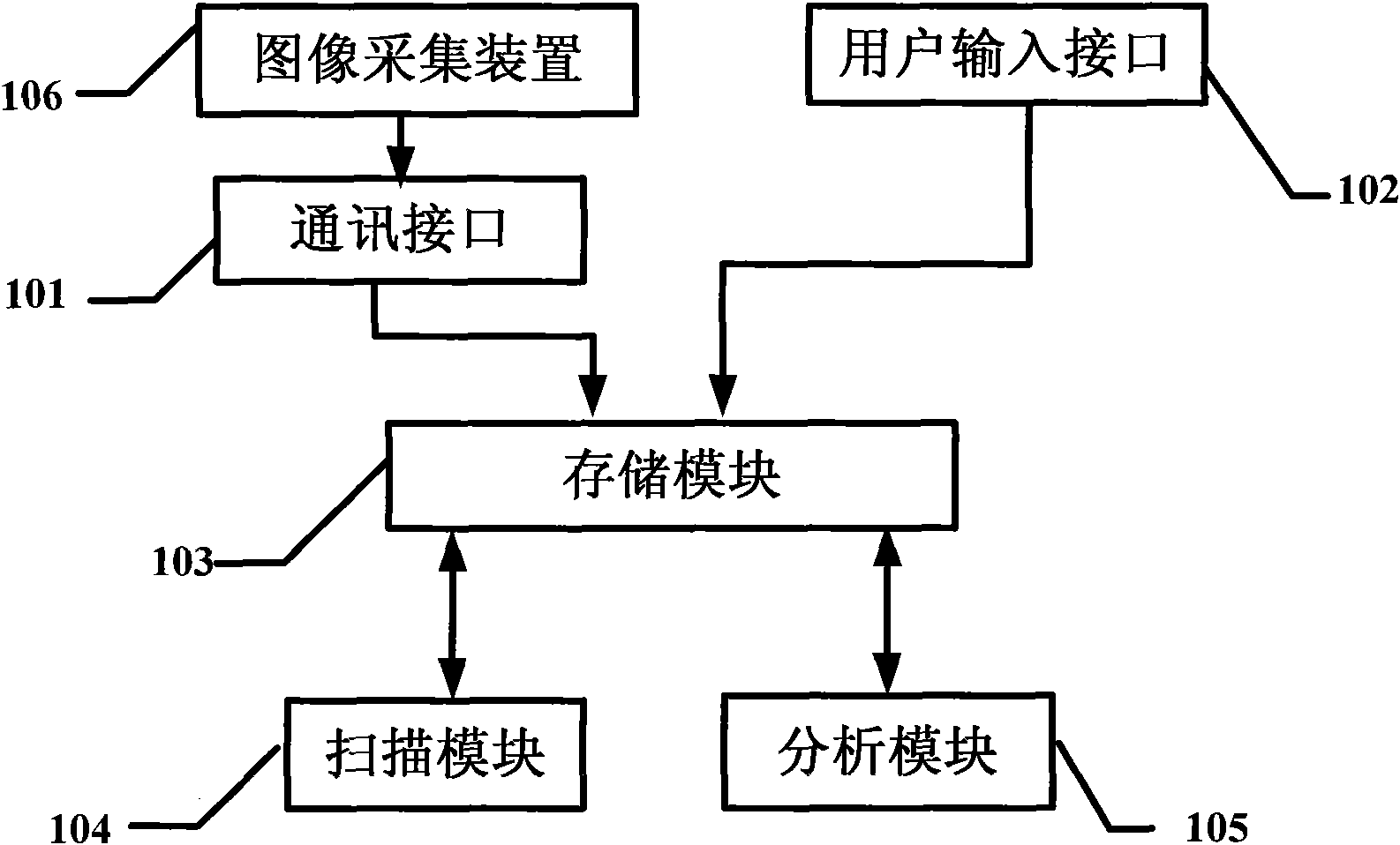
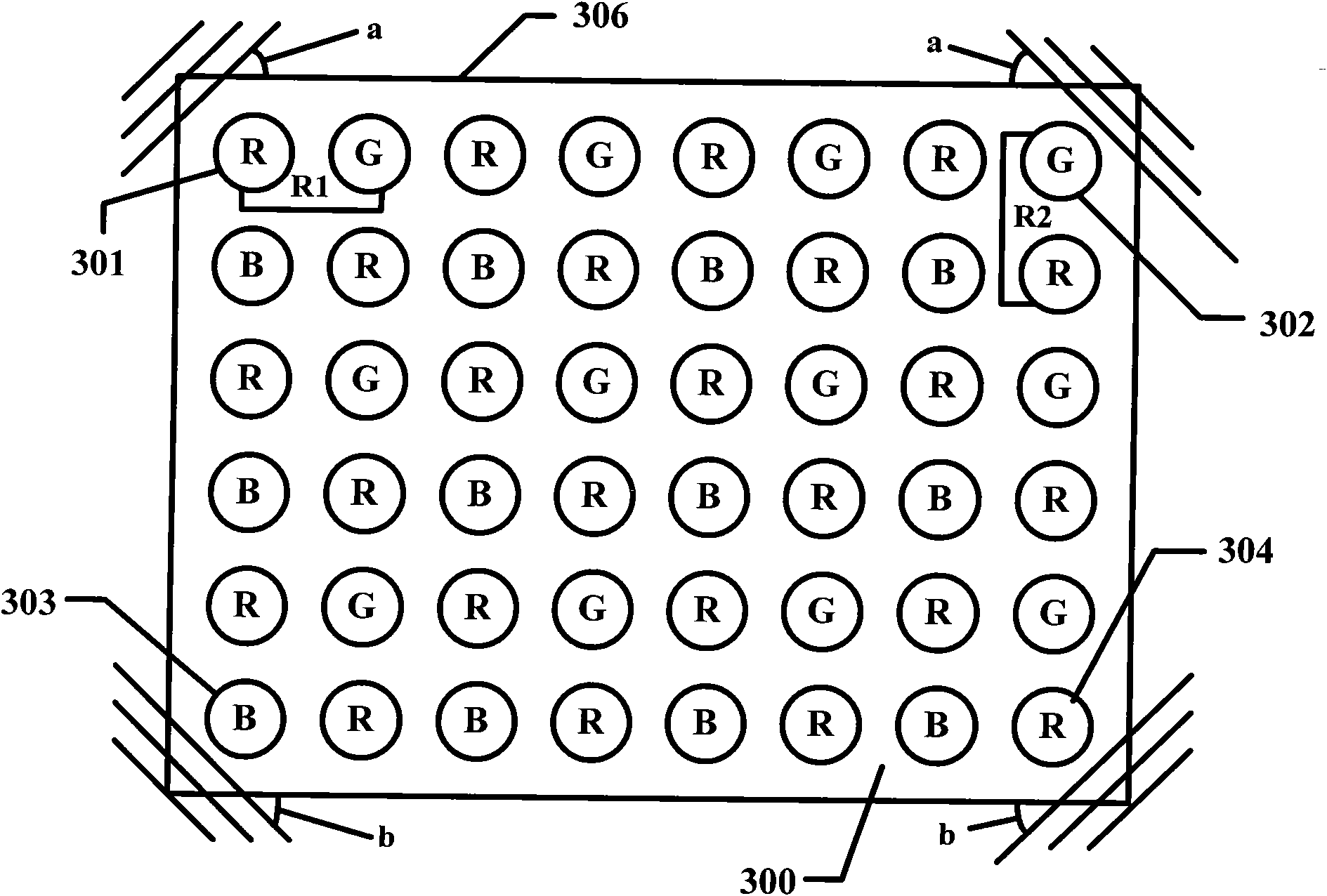
[0036] refer to image 3 with Figure 4 , the present invention provides a method for detecting the uniformity of display screen pixels. In the figure, an LED display screen 306 with a resolution of 6×8, that is, the display screen has 6 rows and 8 columns of light points; and it is necessary to ensure that the The LED lights at the four terminals of the display screen 306 work normally, and then the photo information of the display screen is stored to the storage module 103 through the communication interface 101 . The resolution of the display screen and the reference threshold are input through the user input interface 102 , and the resolution is 6×8 and the reference threshold is 55 and stored in the storage module 103 .
[0037] It should be noted that the reference threshold can be adjusted according to actual conditions.
[0038] The scanning module 104 reads the reference threshold value and the display screen photo information in the storage module 103, from the upp...
Embodiment 2
[0045] refer to image 3 with Figure 4 As shown, the difference from Embodiment 1 is that the analysis module 105 reads the resolution information 6×8 and the coordinate values of the pixel point 301, the pixel point 302, the pixel point 303 and the pixel point 304 in the storage module 103, according to The following calculation formula calculates the row center distance R1 and the column center distance R2 of the display screen and stores them in the memory module;
[0046] The row center distance R1=(coordinate of lower right end point-coordinate of lower left end point) / (number of display screen columns-1)=(8.5-1.1) / (8-1)=1.06;
[0047] The row center distance R2=(row coordinate of upper left end point−row coordinate of lower left end point) / (row number of display screen−1)=(8.8-3.8) / (6-1)=1.
[0048] In this embodiment, the scanning module 104 reads the column center distance R1, the row center distance R2 and the reference threshold in the storage module 103, from ...
Embodiment 3
[0050] refer to image 3 with Figure 4 As shown, the difference from Embodiment 1 is that the row center distance R1 and the column center distance R2 of the display screen are calculated according to the following calculation formula and stored in the storage module;
[0051] The column center distance R1=[(coordinates of the upper right endpoint column-coordinates of the upper left endpoint) / (number of display columns-1)+(coordinates of the lower right endpoint-coordinates of the lower left endpoint) / (number of columns of the display panel-1) ] / 2=1.045;
[0052] Described line center distance R2=[(row coordinate of upper right end point-row coordinate of lower right end point) / (row number of display screen-1)+(row coordinate of upper left end point-row coordinate of lower left end point) / (row number of display screen-1) ] / 2=1.02.
[0053] In this embodiment, the scanning module 104 reads the center distance and the reference threshold in the storage module in the storage...
PUM
 Abstract
Description
Claims
Application Information