Eureka AIR delivers breakthrough ideas for toughest innovation challenges, trusted by R&D personnel around the world.

Indicator for dust collector

A vacuum cleaner and indicator technology, applied in the direction of suction filters, magnetic objects, electrical components, etc., can solve the problems of air flow obstruction, small air flow, indicator sealing and large magnetic force, etc., to ensure normal operation, prolong service life, and facilitate The effect of communalization

Inactive Publication Date: 2010-03-03
LG ELECTRONICS (TIANJIN) APPLIANCES CO LTD
View PDF0 Cites 2 Cited by
  • Summary
  • Abstract
  • Description
  • Claims
  • Application Information

AI Technical Summary

Problems solved by technology

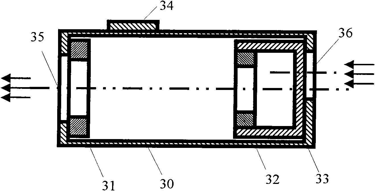
Since the distance between the first magnetic body 31 and the second magnetic body 32 shown in the figure is relatively long, a relatively large magnetic force is required to seal the indicator, so it is necessary to use the highest level of permanent magnets, currently the highest High-grade permanent magnets are expensive, causing the cost of vacuum cleaner indicators to rise significantly
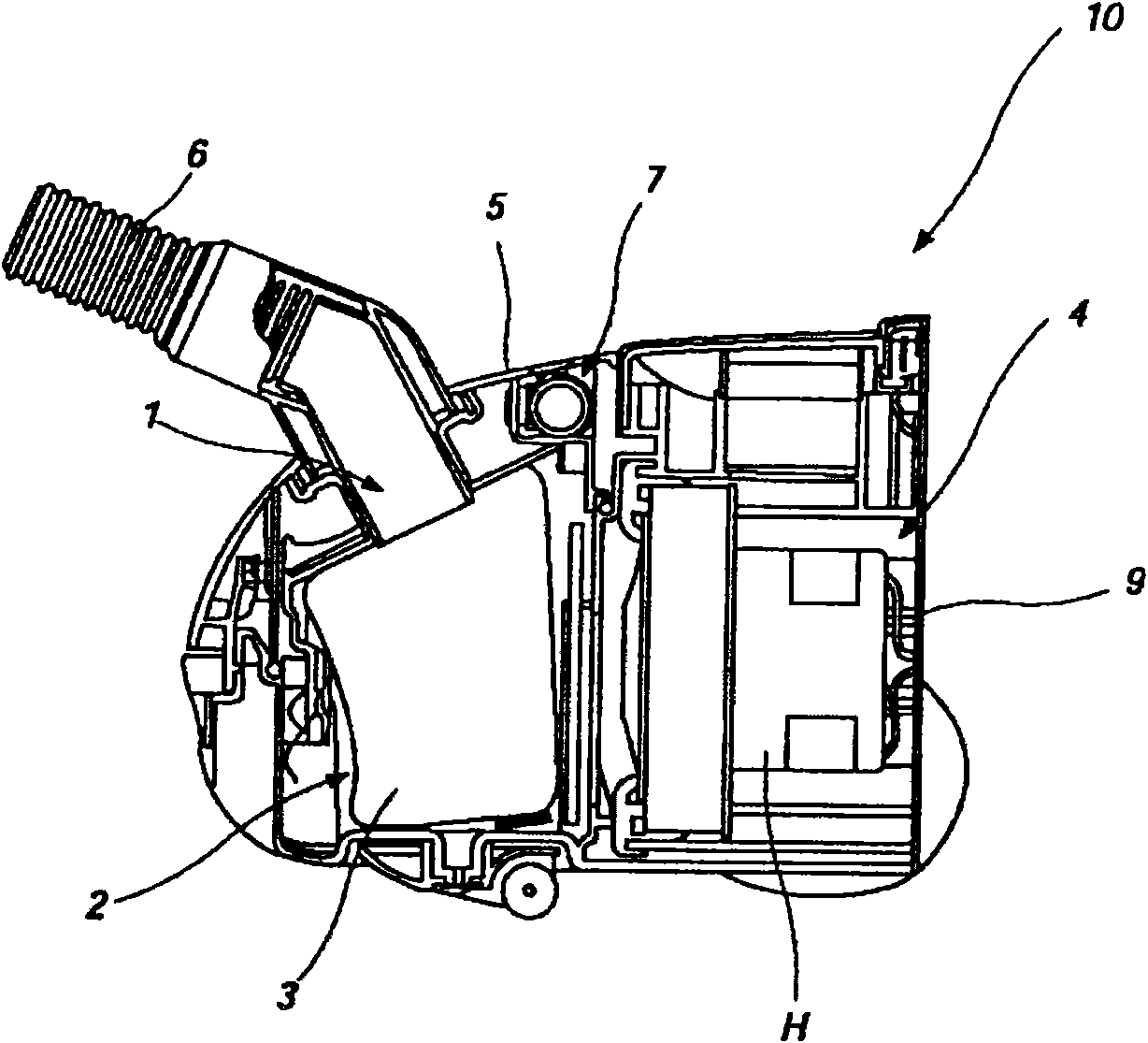
In addition, if foreign matter is accumulated in the dust bag 3, the flow of air flowing into the vacuum cleaner from the suction port 1 and the suction hose 6 will be hindered, resulting in the reduction of the air pressure in the dust collection space 2 and turning it into a vacuum state. Under the action of atmospheric pressure, the pointer 33 gradually moves towards the observation window. Since the repulsion between the first magnetic body 31 and the second magnetic body 32 is inversely proportional to the distance, after the pointer 33 moves, this The repulsive force between the two magnetic bodies increases, which hinders the further action of the indicator 33, so that the indicator 33 cannot normally reach the position of the observation window 34, and the indicator cannot correctly indicate the different vacuum degrees inside the vacuum cleaner. Thereby the user can't understand in time through the observation window 34 the change of the amount of foreign matter such as dust collected by the dust bag 3
[0010] In addition, the indicator of the vacuum cleaner, when the indicator body 33 moves, because the air flowing in at the air inlet 36 flows into the indicator through the gap between the indicator body 33 and the inner wall of the indicator housing 30, thus, the outside of the vacuum cleaner The air flow through the indicator into the dust collection space is small, and since the air flow from the suction port 1 and the suction hose 6 into the vacuum cleaner has been hindered, the air flow through the indicator cannot cool the motor in time The requirements of the vacuum cleaner motor inside the shell H seriously affect the service life of the vacuum cleaner motor

Method used


Image

  • Indicator for dust collector
  • Indicator for dust collector
  • Indicator for dust collector

Examples


Embodiment Construction

[0029] In order to enable those skilled in the art to better understand the solution of the present invention, the present invention will be further described in detail below in conjunction with the accompanying drawings and embodiments.

[0030] see Figure 4 , Figure 5 , Figure 6 An indicator of a vacuum cleaner provided by the present invention includes an outer casing 40 and a lever 41, a rotating shaft 42 is arranged on the upper left end of the outer casing 40, and the lever 41 is rotatably mounted on the said rotating shaft 42. The upper side of the left end of the outer casing 40 .

[0031] A transparent observation window 47 for observing the internal state of the indicator protrudes from the upper side of the indicator outer shell 40, and an air outlet 43 and an air inlet 44 are respectively provided on the left and right sides of the outer shell 40 , when the lever 41 is opened, the air outlet 43 communicates with the dust collecting space 2 inside the vacuum cle...


PUM


Abstract

The invention discloses an indicator for a dust collector. The indicator comprises a housing body and a lever, wherein the upper side at the left end of the housing body is provided with a rotating shaft; the lever is rotatably arranged on the upper side at the left end of the housing body via the rotating shaft; the upper side of the housing body of the indicator is provided with an observation window in a projecting way for observing the internal state of the indicator; the left side and the right side of the housing body are provided with an air outlet and an air inlet respectively; the airoutlet is communicated with the inside of the dust collector, and the air inlet is communicated with the outside of the dust collector; the lower side of the housing body positioned below the air outlet is provided with a second magnetic body; one end of the lever far away from the rotating shaft is provided with a first magnetic body; the first magnetic body and the second magnetic body are oppositely arranged; and the inside of the housing body is also provided with an indication body. The indicator can indicate different vacuum degrees in the indicator, so that a user knows the quantity variation situation of foreign materials collected by a dust bag via the observation window. Moreover, the indicator has low cost, and is beneficial for production and popularization.

Description

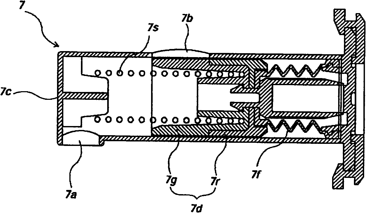
technical field [0001] The invention relates to the technical field of mechanical dust removal, in particular to an indicator of a vacuum cleaner. Background technique [0002] Such as figure 1 As shown, a general vacuum cleaner 10 body includes a motor drive chamber 4 and a dust collection space 2 . The motor housing H with a fan (not shown) and a motor (not shown) that generates suction is installed in the above-mentioned motor drive chamber 4 . An exhaust member 9 is provided at the rear of the motor housing H to exhaust the air separated from the foreign matter to the outside of the vacuum cleaner 10 body. [0003] A suction inlet 1 is formed on the front side of the dust collection space 2 in front of the above-mentioned motor drive chamber 4, and a motor and a fan that can generate suction are provided between the dust collection space 2 and the exhaust member 9, so that the suction inlet 1 and The suction hose 6 connected to the suction inlet forms a suction force,...

Claims


Application Information

Patent Timeline
Patent Type & Authority Applications(China)
IPC IPC(8): A47L9/19H01F7/00
Inventor 张国勇吕新
Owner LG ELECTRONICS (TIANJIN) APPLIANCES CO LTD
Why Eureka
Eureka Blog
Learn More