Micro-particle diffusing device

A diffusion device and particle technology, which is applied in the direction of capturing or killing insects, heating methods, animal husbandry, etc., can solve the problems of reducing ions and reducing bactericidal performance

Active Publication Date: 2013-12-18
SHARP KK
View PDF1 Cites 0 Cited by
  • Summary
  • Abstract
  • Description
  • Claims
  • Application Information

AI Technical Summary

Problems solved by technology

Positive ions and negative ions disappear when they collide, and there is a problem that the

Method used


Image

  • Micro-particle diffusing device
  • Micro-particle diffusing device
  • Micro-particle diffusing device

Examples


Embodiment Construction

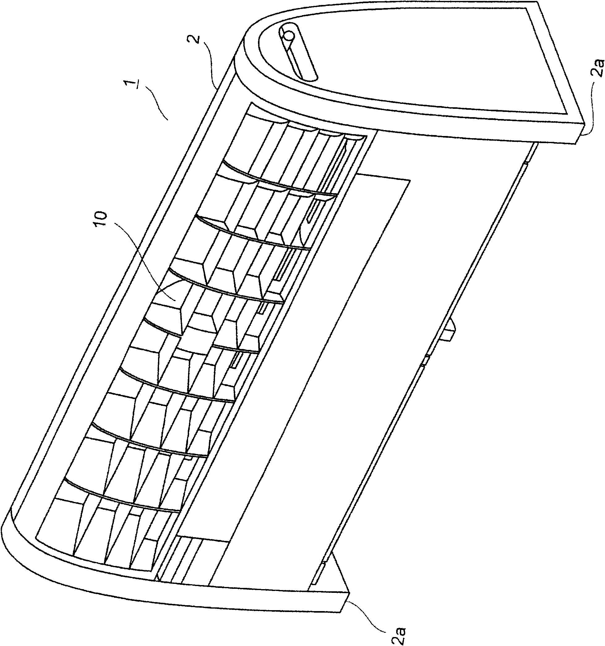
[0091] Embodiments of the present invention will be described below with reference to the drawings. figure 1 It is an external perspective view showing the microparticle diffusion device according to the first embodiment of the present invention. The microparticle diffusion device 1 is composed of an ion diffusion device that diffuses and sends out ions. The microparticle diffuser 1 is provided with leg portions 2a at both left and right ends of the main body housing 2, and is installed on the floor in a living room. An air outlet 10 is opened in the front upper portion of the main body case 2 .

[0092] figure 2 A side cross-sectional view of the microparticle diffusion device 1 is shown. On the bottom surface of the main body case 2, a suction port 3 for sucking in the air in the living room is provided. The fan 5 covered by the case 5a is arrange|positioned at the lower part of the main body case 2. As shown in FIG. The fan 5 is constituted by a cross-flow fan, sucks ...


PUM


Abstract

The invention provides a micro-particle diffusing device. The micro-particle diffusing device is provided with first discharge openings (10a-10c) for discharging first airflows to the upper part of anindoor living space, a second discharge opening (10d) provided below the first discharge openings (10a-10c) and discharging a second airflow to below the first airflows, and a micro-particle generating device (17) for generating micro-particles. The micro-particles generated by the micro-particle generating device (17) are discharged indoors, and the concentration of micro-particles discharged from the first discharge openings (10a-10c) is set lower than the concentration of micro-particles discharged from the second discharge opening (10d). So that the first airflows become an atmosphere screen, for preventing the diffusion of the micro-particles contained in the second airflows to the upper space of the living space. Therefore, a great deal micro-particles generated by the micro-particle generating device to the living space, to obtain better sterilizing, relaxing or the like effects.

Description

technical field [0001] The present invention relates to a microparticle diffuser that sends out microparticles and diffuses the microparticles into a chamber. Furthermore, the present invention also relates to a microparticle diffusion device for emitting ions and diffusing the ions into a chamber. Background technique [0002] In Patent Document 1 (Japanese Patent Laid-Open Publication No. 3797993 (page 4-page 18, figure 1 , Figure 20 )) discloses a conventional particle diffusion device. In front of the particle diffuser, a fan is arranged in a box with an air outlet, and the fan and the air outlet are connected through an air supply path. A particle generating device that generates ions that are particles is arranged in the air blowing path. [0003] The airflow generated by the fan flows through the air supply path, and the airflow containing the particles generated by the particle generating device is sent out from the outlet. The air supply path is made to widen ...

Claims


Application Information

Patent Timeline
IPC IPC(8): A61L9/22A61L9/12A61L2/22A01M13/00F24F1/00
Inventor 大塚雅生苅田英之
Owner SHARP KK
Why Eureka
Try Eureka