Method and equipment for configuring maintenance end points
A technology for maintaining endpoints and client devices. It is applied in the branch office to provide special service devices, data exchange through path configuration, and data exchange details. It can solve problems such as error-prone and low efficiency, and reduce workload and improve configuration. successful effect
- Summary
- Abstract
- Description
- Claims
- Application Information
AI Technical Summary
Problems solved by technology
Method used
Image

Examples
Embodiment 1
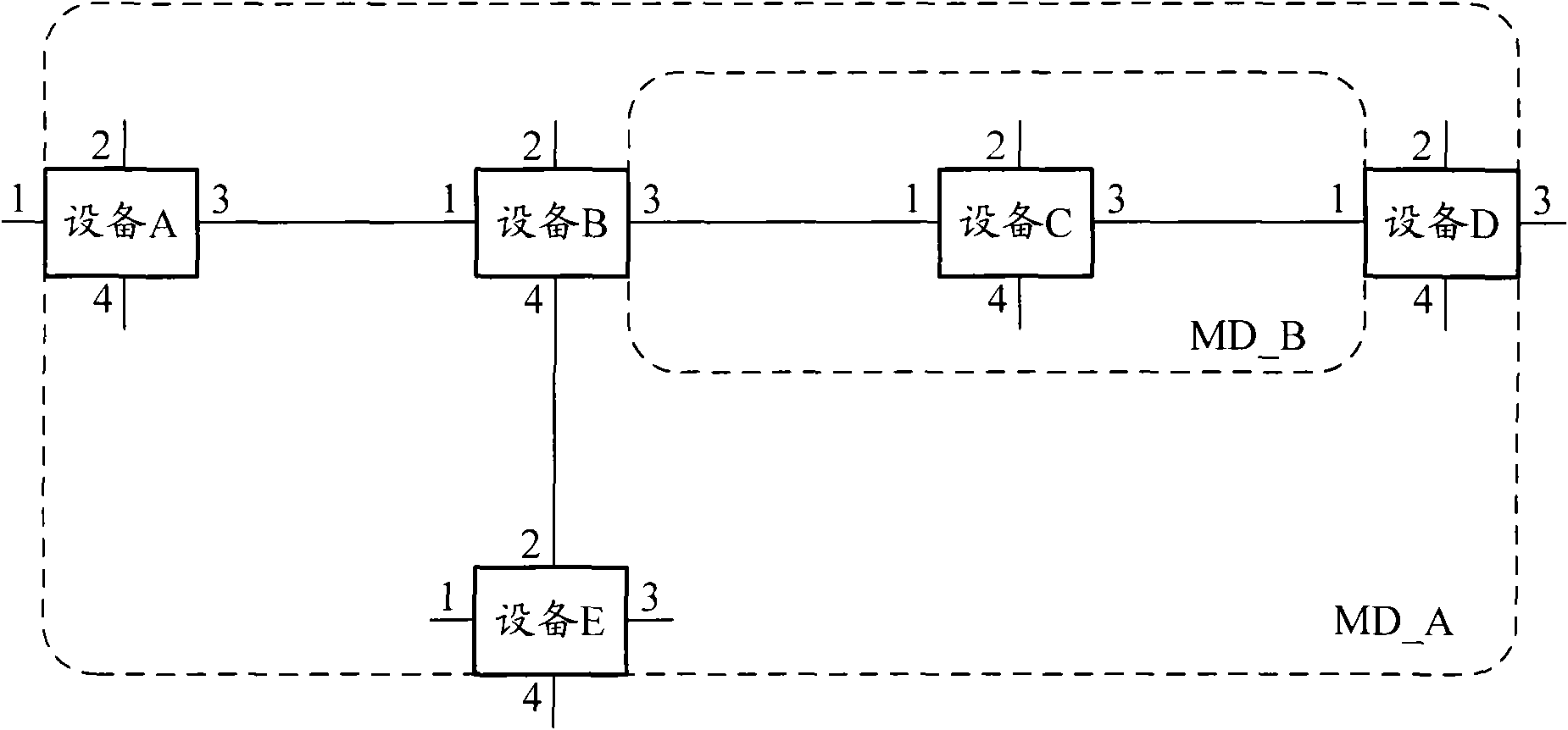
[0087] In this embodiment, the user needs to determine all devices that need to apply the CFM mechanism for connectivity detection according to the network planning in advance, and then divide the corresponding maintenance domain, and determine the maintenance domain level (Level) of the maintenance domain, and the maintenance domain in the maintenance domain. Information such as the maintenance set and the VLAN served by the maintenance set. Then, select a device (hereinafter assumed to be the second device) from all the above-mentioned devices, configure the device as the MEP server, and the device as the MEP server can respond to the specific message sent by the MEP client. Then, configure the MEP on the MEP server according to the complete MEP configuration process in the prior art. All devices except the MEP server are configured as MEP clients. The MEP clients can send specific messages to request the MEP server to deliver corresponding MEP configuration parameters, and ...
Embodiment 2
[0107] In this embodiment, the relevant configuration of the MEP is implemented through four messages exchanged between the MEP client and the MEP server. Using more interactive packets can improve the reliability of MEP configuration
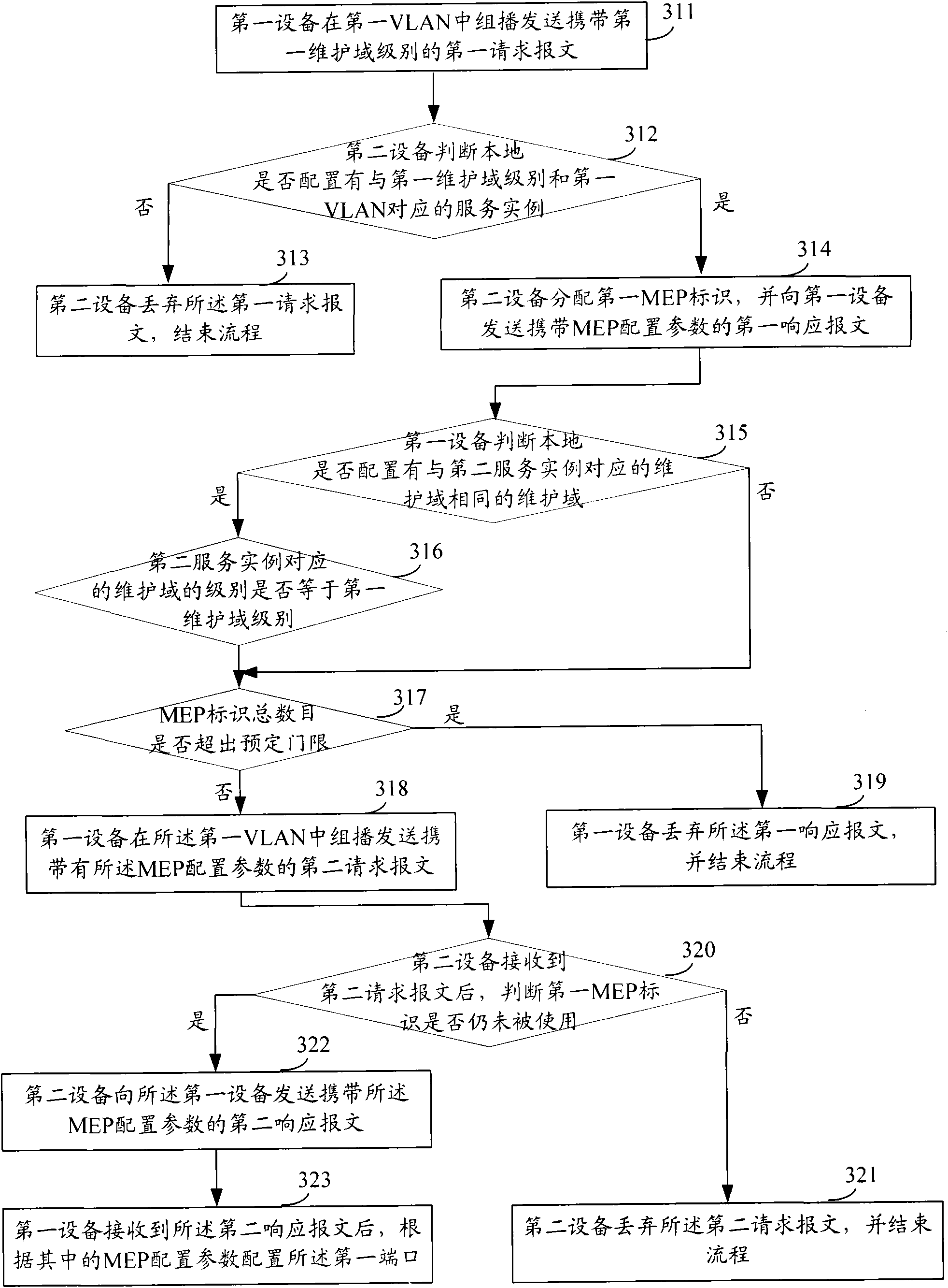
[0108] Similar to Embodiment 1 above, in this embodiment, the first device is an MEP client and the second device is an MEP server as an example for description. Please refer to image 3 , the method for configuring the MEP described in this embodiment includes the following steps:
[0109] Step 311, when the first device configured as a MEP client needs to configure its first port as the first MEP, according to the predetermined first VLAN corresponding to the first MEP, the first maintenance domain level, and the first direction, A first request packet carrying the first maintenance domain level is multicast sent in a VLAN.
[0110] Here, the second request packet may be sent multiple times at specific time intervals. When the first direc...
Embodiment 3
[0165] Based on the methods for configuring an MEP provided in the above two embodiments, this embodiment provides an MEP client device and an MPE server device.
[0166] Among them, such as Figure 4 As shown, the MEP client 40 provided in this embodiment includes:
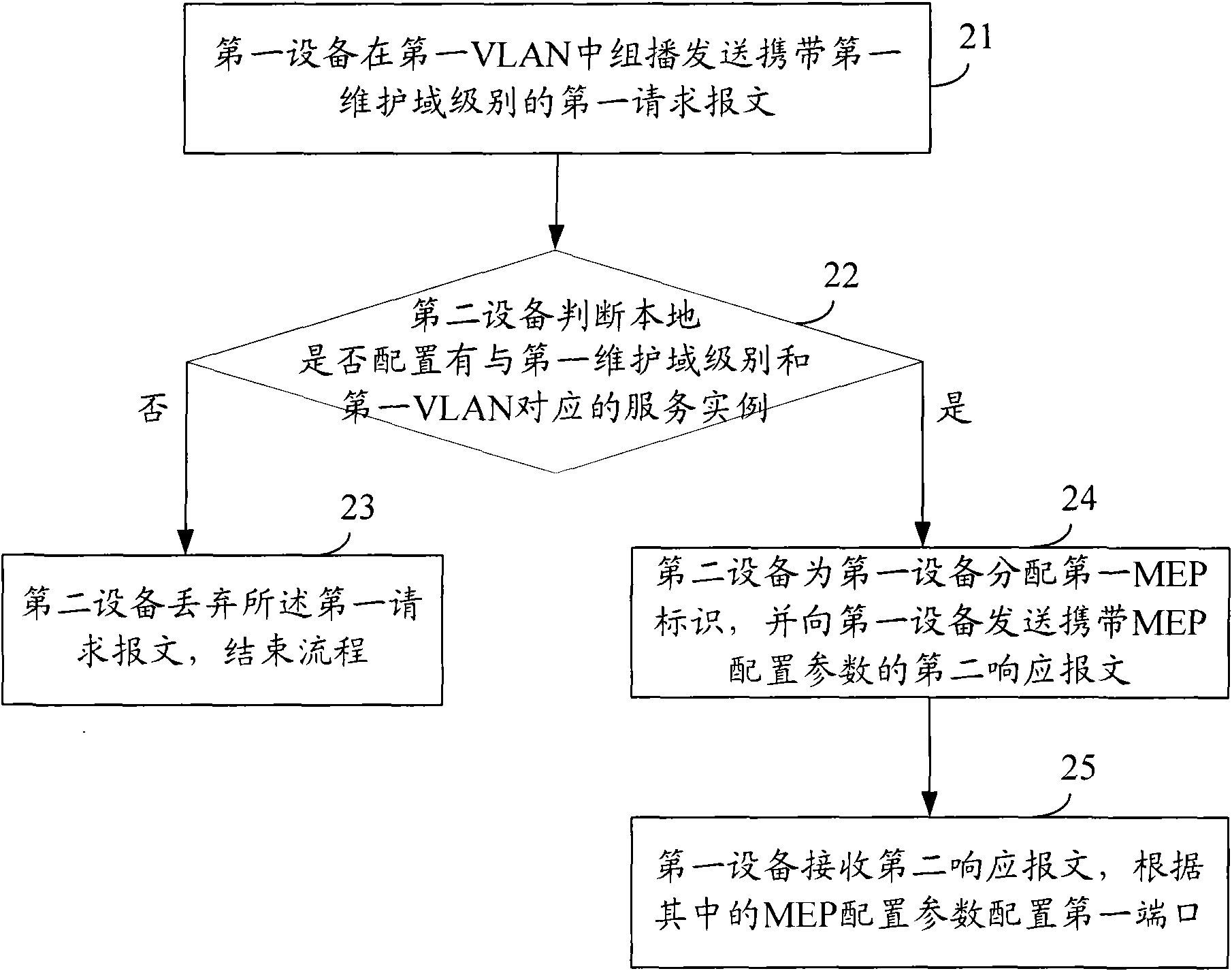
[0167] The first sending unit is configured to, when it is necessary to configure the first port of the device as the first MEP, according to the predetermined first VLAN corresponding to the first MEP, the first maintenance domain level, and the first direction, group in the first VLAN Sending the first request message carrying the first maintenance domain level by broadcast;
[0168] The second receiving unit is configured to receive a second response message carrying MEP configuration parameters returned by the MEP server device, where the MEP configuration parameters include a first MEP identifier, and the first MEP identifier is the After the first request message is received in the first VLAN, an unused M...
PUM
 Abstract
Description
Claims
Application Information
 - R&D
- Intellectual Property
- Life Sciences
- Materials
- Tech Scout
- Unparalleled Data Quality
- Higher Quality Content
- 60% Fewer Hallucinations
Browse by: Latest US Patents, China's latest patents, Technical Efficacy Thesaurus, Application Domain, Technology Topic, Popular Technical Reports.
© 2025 PatSnap. All rights reserved.Legal|Privacy policy|Modern Slavery Act Transparency Statement|Sitemap|About US| Contact US: help@patsnap.com