Automobile glass lifter

An automotive glass and lifter technology, applied in windshields, vehicle parts, windows, etc., can solve the problems of easy wear of pulleys, unstable operation of lifters, and easy deformation of guide rails, so as to prolong the life time, reduce the The effect of product quality failures

Inactive Publication Date: 2010-03-10
SAIC-GM-WULING AUTOMOBILE CO LTD
View PDF1 Cites 3 Cited by
  • Summary
  • Abstract
  • Description
  • Claims
  • Application Information

AI Technical Summary

Problems solved by technology

[0006] In order to solve the problem that the lifter in the prior art is not running smoothly, the pulley is easily

Method used


Image

  • Automobile glass lifter
  • Automobile glass lifter
  • Automobile glass lifter

Examples


Embodiment Construction

[0019] The technical solution of the present invention will be explained in conjunction with the accompanying drawings and embodiments as follows:

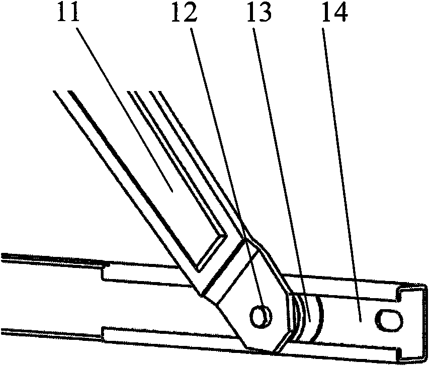
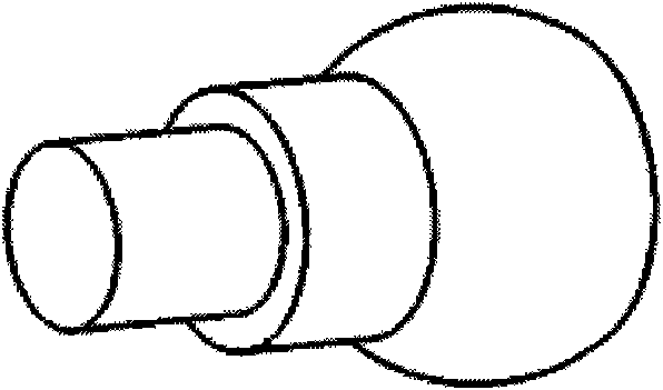
[0020] Such as Figure 4 with 5 As shown, the names of the components are as follows:

[0021] The jib 1, the rotating shaft 2, the sliding block 3, the fixed guide rail 4, the tooth plate 5, the motor 6, the movable guide rail 7, the spline shaft 8, the main arm 9, the base plate seat shaft 10, the main arm or the auxiliary arm 21, and the guide rail 22.

[0022] A glass lifter for automobiles includes a main arm 9, a jib 1, a fixed guide rail 4, a movable guide rail 7, a gear plate 5, a motor 6, a base shaft 10, a rotating shaft 2, a sliding block 3, and one end of the main arm 9 is fixed with a The tooth plate 5 driven by the motor 6, the other end is clamped in the moving rail 7 by the slider 3, one end of the jib 1 is clamped in the moving rail 7 by the slider 3, and the other end is clamped in parallel with the moving rail 7 by the...


PUM


Abstract

The technical scheme of the invention relates to an automobile glass lifter comprising a main arm, an auxiliary arm, a fixed guide rail, a movable guide rail, a toothed plate, an electric motor, a bottom plate seat shaft and sliding blocks. One end of the main arm is fixed by toothed plate which can be driven by the electric motor, and the other end is clamped in the movable guide rail by one sliding block; one end of the auxiliary arm is clamped in the movable guide rail by another sliding block, and the other end is clamped in the fixed guide rail which is arranged parallel to the movable guide rail by still another sliding block; the main arm and the auxiliary arm are connected by a shaft pin and can rotate round the shaft pin; and the sliding blocks contact the fixed guide rail and the movable guide rail on surface. Because the sliding blocks contact the fixed guide rail and the movable guide rail on surface, the problems concerning the easy deformation of the guide rails and the easy abrasion and invalidation of the pulleys of the prior automobile glass lifter and even the unstable running of the prior automobile glass lifter are solved, and further the service lives of the components are prolonged and the quality fault of the product is decreased.

Description

【Technical Field】 [0001] The technical scheme of the present invention relates to a window of a vehicle, in particular to an improvement of a window lifter. 【Background technique】 [0002] A utility model patent application with the patent number 02264507.1 discloses a window lifter, which describes a relatively common structure of the existing window lifter. [0003] At present, many door and window lifters at home and abroad have round pulleys for the main arms and jibs. When the lifter is working, the circular pulleys roll back and forth in the guide rail and support the guide rail to drive the glass to move up and down. The supporting contact between the pulley and the guide rail is point-line contact. [0004] The pulleys of the main and jib of the lifter are round, as shown in figure 1 Shown. Among them: main arm or auxiliary arm 11, rotating shaft 12, sliding block 13, guide rail 14. After the slider is put on the rotating shaft, one end of the rotating shaft is riveted to ...

Claims


Application Information

Patent Timeline
IPC IPC(8): E05F15/16B60J1/17B60J1/20E05F15/689
Inventor 周余瑾危学兵
Owner SAIC-GM-WULING AUTOMOBILE CO LTD
Why Eureka
Try Eureka