Supercharge Your Innovation With Domain-Expert AI Agents!

Vacuum pipeline

A vacuum pipeline and vacuum technology, applied in the field of fluid conveying pipelines and pipelines, can solve the problems of increased cold loss of joints, large vacuum interlayer space, and short straight-line distance, etc., and achieve reliable sealing effect

Active Publication Date: 2010-12-08
启东市海鹰冶金机械有限公司
View PDF2 Cites 0 Cited by
  • Summary
  • Abstract
  • Description
  • Claims
  • Application Information

AI Technical Summary

Problems solved by technology

[0004] It can be seen from the analysis that the disadvantages of the above-mentioned prior art are that not only the connection is not convenient enough, but also the tightness of the connection is still not ideal. In addition, there are the following problems: 1), because two heat insulating sleeves are arranged between the inner pipe and the outer pipe, Therefore, there needs to be enough space, and the diameter difference between the inner tube and the outer tube is bound to be large, which directly leads to a large vacuum interlayer space, which is not good for pumping and maintaining the vacuum degree of the vacuum pipeline. At the same time, the raw material consumption of the outer tube is large, which increases the cost. ; 2), because the sealing joint of the inner pipe is closer to the sealing joint of the outer pipe, the straight-line distance between the two joints is short, and the joint cannot be vacuumed, so there is air, which leads to the increase of the cold loss of the joint part, and the result will accelerate the internal cooling of the pipeline. Vaporization of Cryogenic Liquids

Method used


Image

  • Vacuum pipeline
  • Vacuum pipeline
  • Vacuum pipeline

Examples


Embodiment 1

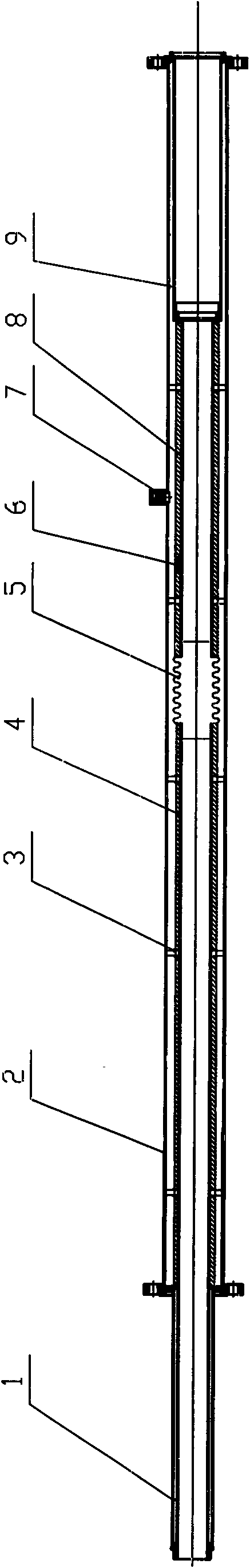
[0017] The vacuum pipeline structure of the present embodiment is as figure 1 As shown, a vacuum is drawn between the inner pipe 4 and the outer pipe 2 sheathed therein. The outer surface of the inner tube 4 is attached with a thermal insulation material 8 and an adsorbent 6 , and its part located in the outer tube 2 is supported on the inner wall of the outer tube by supporting rings 3 arranged at intervals. Since the vacuum pipeline in this embodiment is relatively long, the inner tube is composed of two sections, which are located in the middle of the outer tube and connected by a corrugated compensator, so that the thermal deformation of the inner tube can be supplemented.

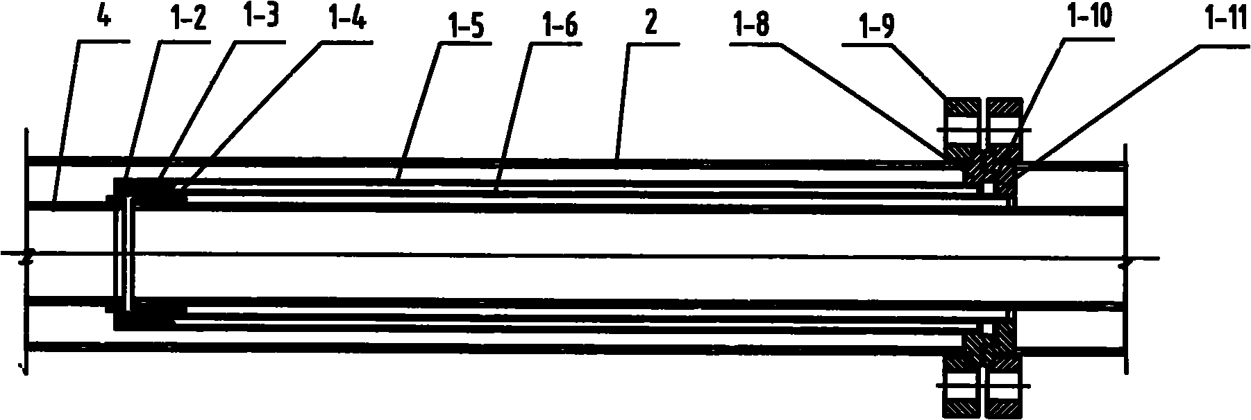
[0018] The two ends of the outer tube 2 are respectively in sealing connection with the first outer flange 1-11 and the second outer flange 1-8 (see figure 2 ). The outer edges of the first outer flange 1-11 and the second outer flange 1-8 form a seam ring that exceeds the outer diameter of the out...


PUM


Abstract

The invention relates to a vacuum pipeline which belongs to the technical field of fluid transportation pipelines. The vacuum pipeline is provided with an inner pipe and an outer pipe; both ends of the outer pipe are respectively connected with a first outer flange and a second outer flange; the outward end surfaces of the first outer flange and the second outer flange are respectively form a depressed part and a convex ring; an inner hole of the first outer flange and one end of an outer connecting pipe are in sealed connection, and the inner hole of the second outer flange and one end of aninner connecting pipe are in sealed connection; the other end of the outer connecting pipe extends into the outer pipe, and the other end of the outer connecting pipe and one end of the inner pipe are in sealed connection through a first inner flange; the other end of the inner connecting pipe extends out of the outer pipe, and the other end of the inner connecting pipe and the other end of the inner pipe extending out of the outer pipe are in sealed connection through a second inner flange; and the outward end surfaces of the first inner flange and the second inner flange respectively form adepressed part and a convex ring. The invention can lead the adjacent pipelines to be conveniently connected, and can ensure the reliable seal of the connecting position of two segments of pipelines through the embedded seal structure of the convex and concave surfaces of the inner and outer flanges.

Description

technical field [0001] The invention relates to a pipeline, in particular to a vacuum pipeline, which belongs to the technical field of fluid conveying pipelines. Background technique [0002] Vacuum pipelines are ideal pipelines for transporting fluids with thermal insulation. But for a long time, the sealed connection between vacuum pipes has always been a problem, and the vacuum pipes also have the problem of easy bursting. [0003] The search found that the Chinese utility model with the application number of 200720186324.4 discloses a connection structure for multi-layer vacuum insulation pipes, including a concave shoulder ring welded to the left outer pipe joint and a shoulder ring welded to the right outer pipe joint. The gasket between the concave and convex shoulder rings and the flanges and bolts for clamping the concave and convex shoulder rings; U-shaped heat sinks are arranged between the outer tube and the inner tube on the left side of the concave shoulder r...

Claims


Application Information

Patent Timeline
Patent Type & Authority Patents(China)
IPC IPC(8): F16L23/032F16L59/14F16L55/00F16L51/02F16L59/065
Inventor 杨裕能
Owner 启东市海鹰冶金机械有限公司
Features
  • R&D
  • Intellectual Property
  • Life Sciences
  • Materials
  • Tech Scout
  • Unparalleled Data Quality
  • Higher Quality Content
  • 60% Fewer Hallucinations
Learn More