Safety electrically heating bag with exhaust valve shelter

A shielding and exhaust valve technology, applied in the field of safe electric heating bags, can solve the problems of scalding users, scalding, gas or liquid overflow, etc., and achieves the effects of convenient opening and closing, convenient operation and simple structure

Inactive Publication Date: 2010-03-10
邓建威
View PDF1 Cites 0 Cited by
  • Summary
  • Abstract
  • Description
  • Claims
  • Application Information

AI Technical Summary

Problems solved by technology

But the electric warm bag of above-mentioned structure still has the following deficiencies: (1), because the exhaust valve is directly exposed on the wall of the bag body, part of the heat of the bag body will be transferred to the exhaust valve after the bag body is heated. When the body is heated, it is easy to touch the exposed exhaust valve and be scalded; moreover, when the bag is used for heating, if the bag is squeezed by excessive force, part of the gas or liquid in the bag will easily overflow through the exposed exhaust valve , while scalding the user

Method used


Image

  • Safety electrically heating bag with exhaust valve shelter
  • Safety electrically heating bag with exhaust valve shelter
  • Safety electrically heating bag with exhaust valve shelter

Examples


Embodiment 1

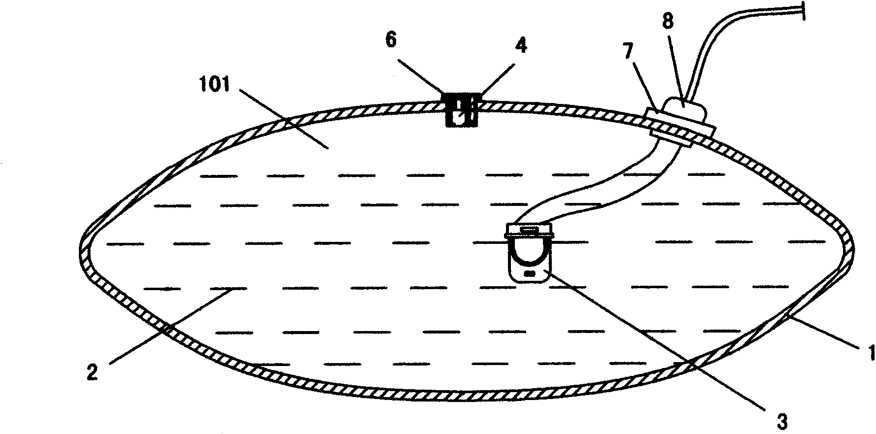
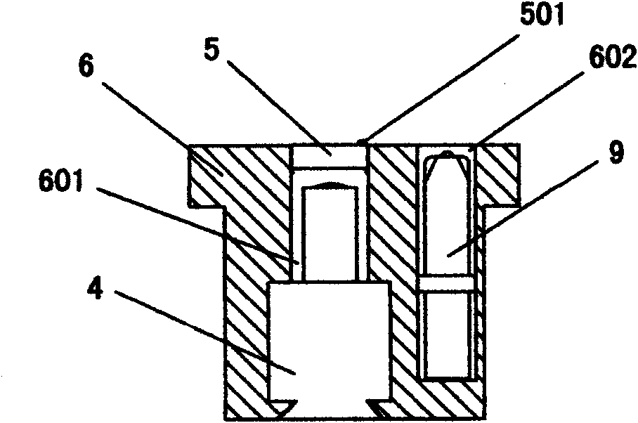
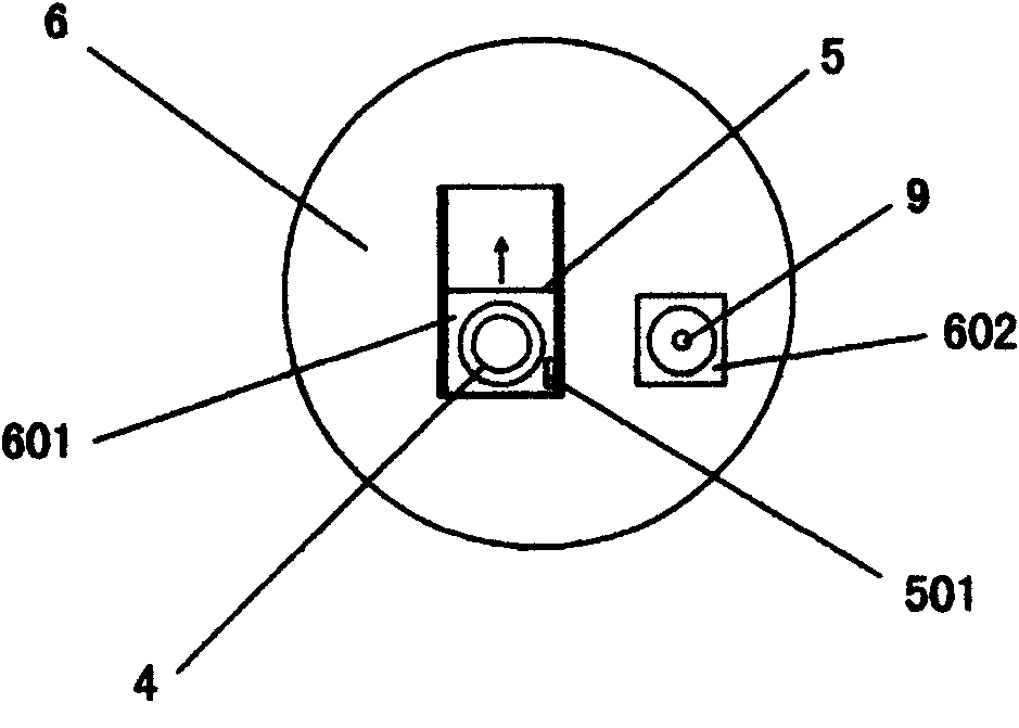
[0022] Embodiment 1: as figure 1 , figure 2 and image 3 As shown, a safety type electric heating heating bag with an exhaust valve shield includes a bag body 1 with a bag cavity 101, a liquid 2 and its electric heating body 3 are arranged in the bag cavity 101, and the wall of the bag body 1 The exhaust valve 4 that can discharge the gas in the bag cavity 101 is installed on the part, and the barrier 5 that can block the exhaust valve 4 by sliding is also installed on the wall of the bag body 1 . Its specific sliding setting method is that the wall of the bag body 1 is also provided with an exhaust valve mounting seat 6, and the exhaust valve mounting seat 6 has a valve body accommodating groove 601 and a valve stem accommodating groove 602, and the valve stem accommodates The exhaust rod tool 9 that can open the exhaust valve 4 to exhaust is placed in the groove 602. The exhaust valve 4 is fixed on the valve body accommodating groove 601 and extends into the bag cavity 10...

Embodiment 2

[0024] Embodiment 2: as Figure 4 As shown, its implementation is similar to that of Example 1, the difference is that the barrier 5 is a transparent arc-shaped sliding cover, and the barrier 5 is installed on the exhaust valve mounting seat through the rotating shaft 10, so that the barrier 5 is arranged on the shaft The rotating slide is installed on the surface of the exhaust valve mounting seat 6 and can cover the valve body accommodating groove 601 . Its working principle is similar to Embodiment 1, and will not be described in detail here.

Embodiment 3

[0025] Embodiment 3: as Figure 5 and Image 6 As shown, its implementation is similar to that of Example 1, the difference is that an electric socket 7 is fixed on the wall of the bag body 1, and an electric plug groove 701 and a valve body accommodating groove 702 are arranged on the electric socket 7, and the exhaust The valve 4 is fixed on the valve body accommodating groove 702 and extends into the bag cavity 101. The electric socket 7 is equipped with a shield 5 that can block the upper opening of the electric plug groove 701 or the valve body accommodating groove 702 by sliding. Wherein, the barrier 5 is installed on the electric plug groove 701 and the upper opening of the valve body accommodating groove 702 on the electric socket 7 in a sliding manner of a horizontal slide rail, so that the electric plug groove 701 needs to be plugged into the power plug 8 before the electric plug groove 701 is energized. The object 5 moves to the upper opening of the valve body acco...


PUM


Abstract

The invention relates to the technical field of electrically heating bags, in particular to a safety electrically heating bag with an exhaust valve shelter, which comprises a bag body with a bag cavity, wherein liquid or an electrical heating body of the liquid are arranged in the bag cavity; the wall part of the bag body is provided with an exhaust valve for exhausting the air in the bag cavity and is also provided with a shelter capable of sheltering the exhaust valve by sliding. By arranging the shelter of the exhaust valve on the wall part of the bag body, the electrically heating bag withthe structure overcomes drawbacks such as user burn caused by the exhaust valve which is directly exposed out of the wall part of the bag body and thus likely to be contacted by people or to lead tothe overflow of part of gases and liquid in the bag when the bag body in use is squeezed by an overlarge force, and the like. In addition, the sliding shelter of the exhaust valve is arranged on the wall part of the bag body, so shelter is easy to pen and close and has a simple and reasonable structure.

Description

technical field [0001] The invention relates to the technical field of electric heating heating bags, in particular to a safety electric heating heating bag with an exhaust valve shield. Background technique [0002] China Utility Model Patent No.: 02272644.6, which discloses a kind of electric heating bag named "An Electric Warm Bag". The authorized announcement date: July 2, 2003. A temperature controller, an over-temperature fuse protector and an electrode in the heat transfer fluid, wherein the temperature controller and the electrode are respectively connected with the over-temperature fuse protector, and the feature is that an external pressure exhaust valve is installed on the bag body. When the bag body needs to be exhausted, it is only necessary to use the exhaust rod (small stick) to press the valve core on the exhaust valve to make it exhaust and release pressure. Therefore, the electric heating bag is not easy to leak liquid and is safe. be improved to a certain...

Claims


Application Information

Patent Timeline
IPC IPC(8): F24D13/02
Inventor 邓建威
Owner 邓建威
Why Eureka
Try Eureka