
Control method for water boiling of electric kettle

A control method and technology for electric kettles, which are applied to water boiling appliances and temperature control using electric methods, and can solve problems such as waste of electric energy, dry heating, and temperature rise of electric heating elements.

Inactive Publication Date: 2010-03-10
余俊忠
View PDF0 Cites 15 Cited by
  • Summary
  • Abstract
  • Description
  • Claims
  • Application Information

AI Technical Summary

Problems solved by technology

[0003] Even so, there is no way to prevent people from taking it from one place to another, which will cause greater problems. For example, when the boiling point of the water in the new place is higher, it will stop when the water is not boiling. Heating phenomenon, another example, when the boiling point of water in a new place is low, the water will continue to boil but the power supply circuit cannot be cut off to stop heating until dry burning occurs, which is not only a waste of electric energy, but also dangerous
[0004] In addition, there is also the problem that the user adds water at the same time during the boiling process of the electric kettle. On the one hand, the temperature is always rising during the boiling process, and on the other hand, adding cold water with a lower temperature will cause The temperature drops instead, which will interfere with the control
[0005] Furthermore, in cold areas, when the temperature is ≤0°C, the water in the electric kettle still absorbs heat while maintaining at 0°C or less than 0°C during the boiling process. , the water is still in the state of freezing, and its fluidity is poor. This will cause the temperature of the electric heating element to rise continuously with the heating process, which will eventually lead to the problem of its own burning

Method used


Image

  • Control method for water boiling of electric kettle
  • Control method for water boiling of electric kettle
  • Control method for water boiling of electric kettle

Examples


Embodiment Construction

[0040] The present invention is described in detail below in conjunction with accompanying drawing:

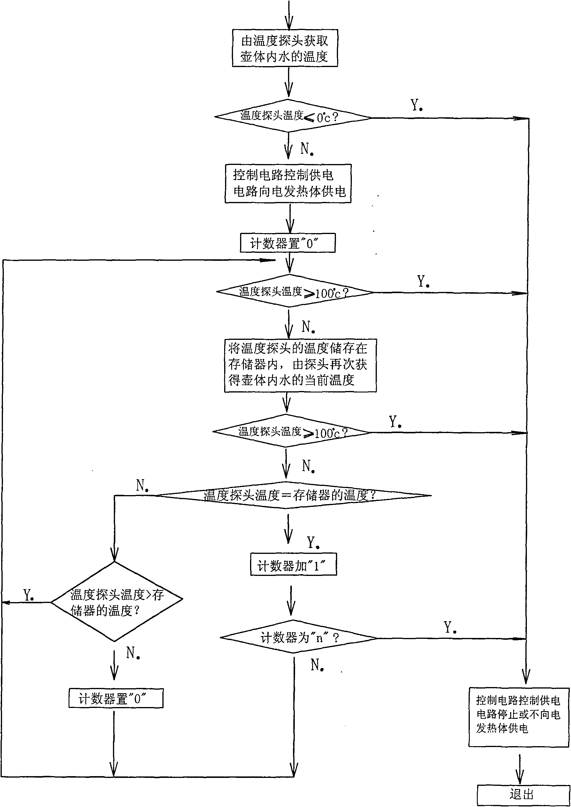
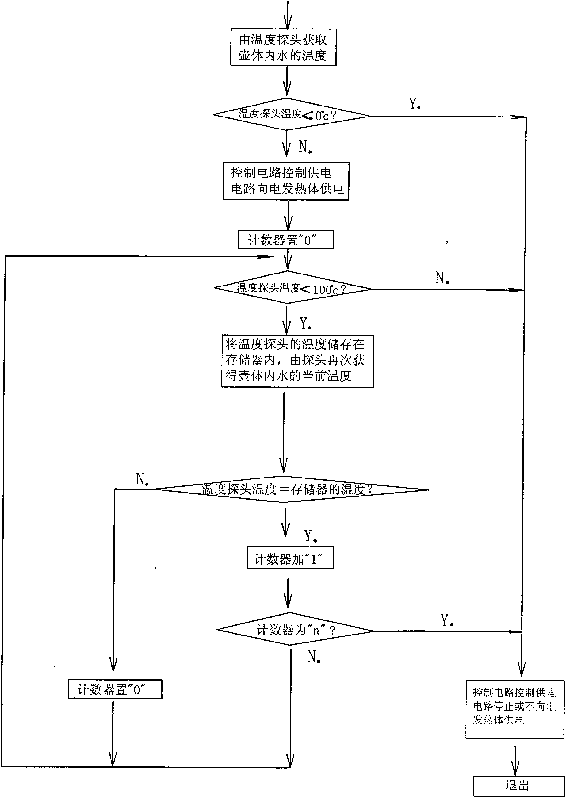
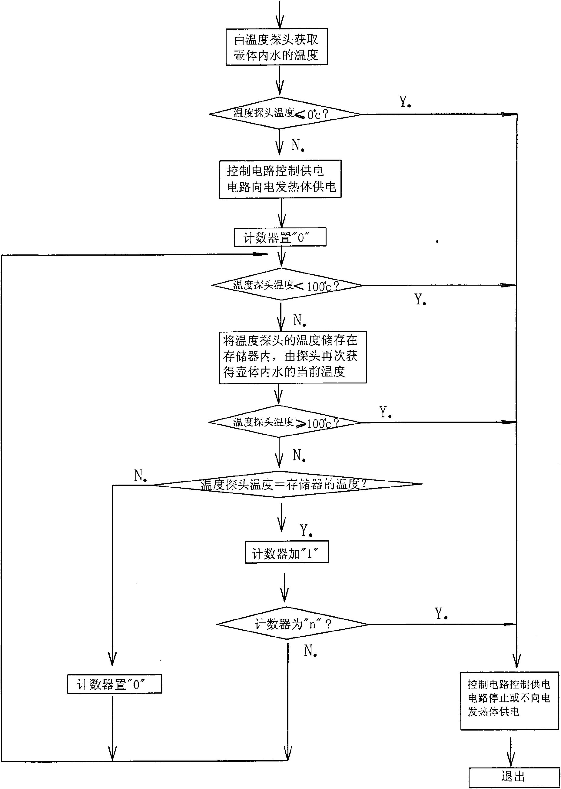
[0041] refer to figure 1 , the control method of this specific electric kettle boiling water adopts the following steps:

[0042] (1) The current temperature of the water in the pot is detected by the temperature probe of the control circuit, and the current temperature of the temperature probe is compared with 0°C. When the current temperature of the temperature probe is ≤0°C, the control circuit controls the power supply circuit not to generate heat When the current temperature of the temperature probe is > 0°C, the control circuit controls the power supply circuit to supply power to the electric heating element, the electric heating element emits heat, and the counter is set to "0";

[0043] (2) Compare the current temperature of the temperature probe with 100°C. When the current temperature of the temperature probe is ≥100°C, the control circuit cuts off the power supply ...


PUM


Abstract

The invention discloses a method for water boiling of an electric kettle, and particularly relates to a control method suitable for water boiling in areas of different altitudes. The method comprisesthe following steps: a control circuit is used for controlling the power supply of a power supply circuit for an electric heating unit which emits heat to a kettle body; a temperature probe of the control circuit is used for detecting the current temperature of water in the kettle body; and in the event that the current temperature measured by the temperature probe does not lower during a certainperiod and maintains constant for a plurality of measuring times, or the current temperature measured by the temperature probe does not change for a plurality of measuring times in succession, the control circuit cuts off the power supply of the power supply circuit for the electric heating unit and withdraws. The method solves the trouble that the temperature of water boiling in different areas needs to be measured one by one and requires setting of the circuit; and simultaneously, the method also prevents the interference of the external world and can eliminate 'false boiling' phenomenon caused by constant temperature during a certain period during heating process, thereby being capable of improving the correctness of boiling control.

Description

technical field [0001] The invention belongs to a method for boiling water in an electric kettle, and relates to the control of boiling water in this boiling process, especially a control suitable for boiling water in different altitude areas and solving the problem of possible conflicts in the adopted schemes, so that The power supply circuit can be accurately and automatically cut off when the water boils. Background technique [0002] At present, electric kettles have been widely used in families or offices. When the electric kettle is used to boil water, when the water boils, the control circuit can automatically cut off the power supply circuit and stop heating. Usually, people do this by constantly comparing the temperature with the boiling point of water. But this requires the manufacturer to measure the boiling temperature of water in various places and set it in the circuit, which makes its manufacture a lot of trouble. [0003] Even so, there is no way to preven...

Claims


Application Information

Patent Timeline
Patent Type & Authority Applications(China)
IPC IPC(8): G05D23/19A47J27/21
Inventor 余俊忠
Owner 余俊忠
Learn More