Detection system and detection method for improving pixel uniformity of display screen
A detection method and detection system technology, applied in the direction of image communication, static indicator, TV, etc., can solve the problems of slow processing speed and achieve the effect of uniformity improvement and convenient resolution
- Summary
- Abstract
- Description
- Claims
- Application Information
AI Technical Summary
Problems solved by technology
Method used
Image

Examples
Embodiment 1
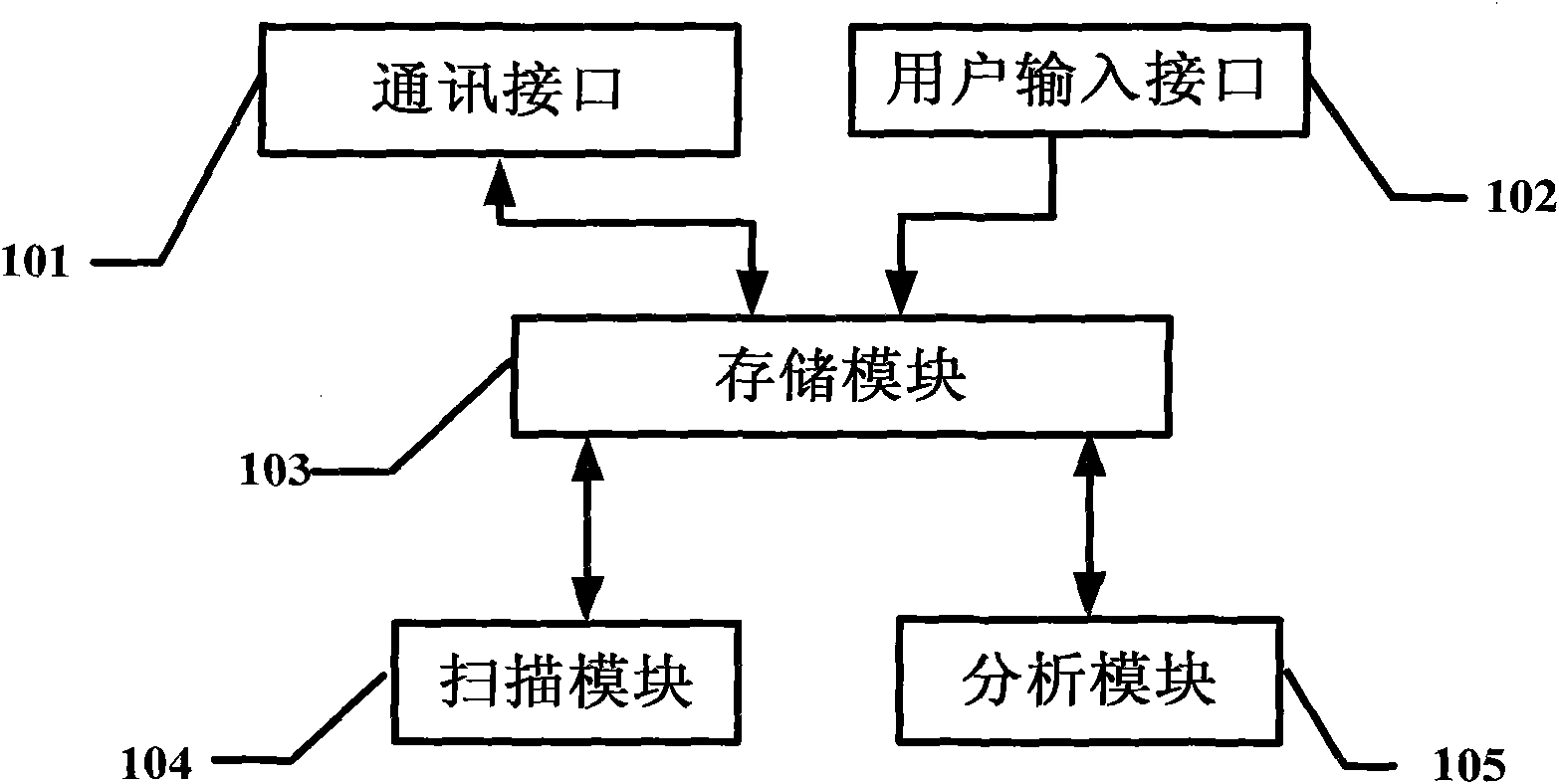
[0047] refer to figure 1 , a detection system for improving the uniformity of display screen pixels, including a communication interface 101, a user input interface 102, an analysis module 105, a scanning module 104, and a storage module 103 connected with the above modules.
[0048] The communication interface 101 is used for two-way data communication, receiving display screen photo information and recording it into the storage module 103 .
[0049] The user input interface 102 is used to input the reference threshold value of the pixel point of the display screen photo and the radius R value of a single light point, and record them into the storage module 103 .
[0050] The scanning module 104 provided with a judging unit is used to read the display screen photo information 300 and the reference threshold from the storage module 103, start scanning from any end corner of the display screen photo, pass the The judging unit judges that the threshold value of a certain pixel ...
Embodiment 2
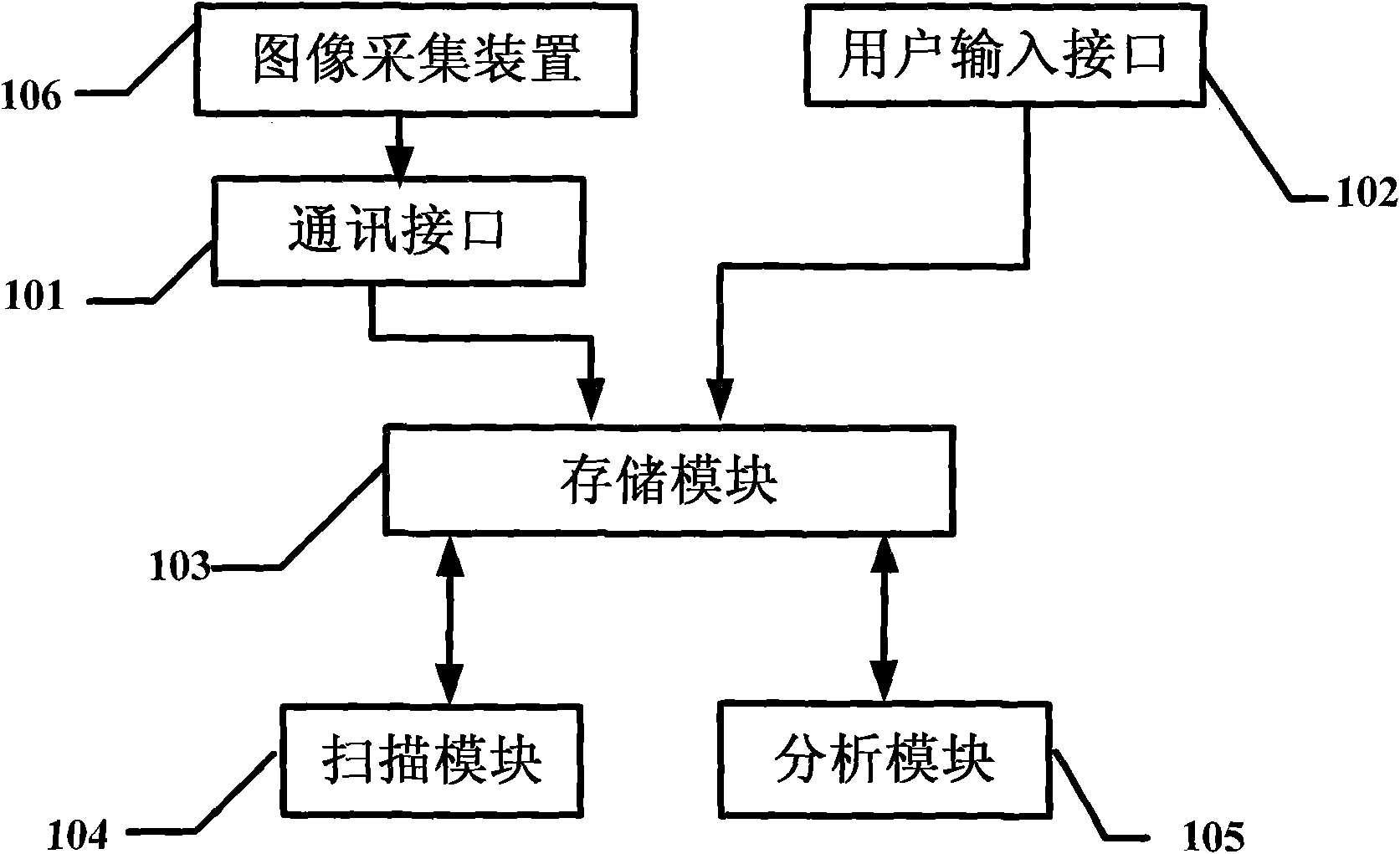
[0056] refer to figure 2 In this embodiment, on the basis of Embodiment 1, the detection system additionally includes an image acquisition device 106, which is used for image acquisition of the display screen to obtain photo information of the display screen, which is stored in the display screen through the communication interface. The above storage module 103. The rest of the principles are the same as those in Embodiment 1, and will not be repeated here.
[0057] The detection system of this embodiment, by installing the image acquisition module 106, can quickly process the photo information of the display screen on site, making the whole detection system more convenient.
Embodiment 3
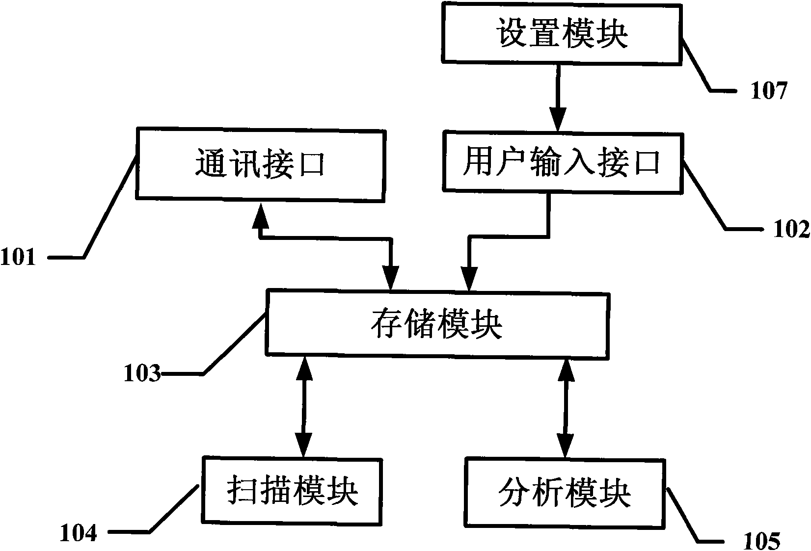
[0059] refer to image 3 In this embodiment, on the basis of Embodiment 1, the detection system additionally includes a setting module 107 connected to the user input interface 102 for selecting or setting the preset rule through the user input interface 102 . The preset sequence is recorded in the storage module 103 . The rest of the principles are the same as those in Embodiment 1, and will not be repeated here. In this embodiment, without departing from the idea of the present invention, the setting module 107 may also be connected to the user input interface and the storage module respectively.
[0060] In the detection system of this embodiment, through the setting module 107, scanning rules and scanning sequences can be conveniently set according to actual conditions, and various scanning rules and various scanning sequences that have been preset can also be directly selected, so as to achieve according to the specific conditions of the photos. The effect of fast pro...
PUM
 Abstract
Description
Claims
Application Information
 - R&D
- Intellectual Property
- Life Sciences
- Materials
- Tech Scout
- Unparalleled Data Quality
- Higher Quality Content
- 60% Fewer Hallucinations
Browse by: Latest US Patents, China's latest patents, Technical Efficacy Thesaurus, Application Domain, Technology Topic, Popular Technical Reports.
© 2025 PatSnap. All rights reserved.Legal|Privacy policy|Modern Slavery Act Transparency Statement|Sitemap|About US| Contact US: help@patsnap.com