Electric ear canal cleaner

A technology for cleaners and ear canals, applied in ear treatment, etc., can solve problems such as troubles and eardrum injuries

Inactive Publication Date: 2010-03-17
CHENGDU JUNFENG TECH DEV
View PDF0 Cites 6 Cited by
  • Summary
  • Abstract
  • Description
  • Claims
  • Application Information

AI Technical Summary

Problems solved by technology

[0002] The existing ear spoon has a thinner tip, which is easy to cause damage to the eardrum
And in the

Method used


Image

  • Electric ear canal cleaner

Examples


Example Embodiment

[0009] The present invention will be further described below with reference to the drawings and embodiments.

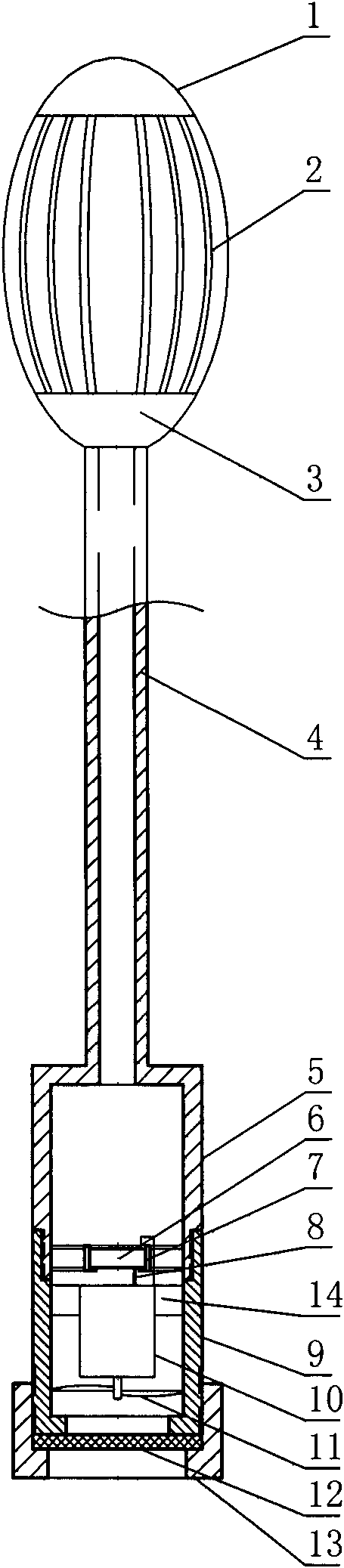
[0010] The electric ear canal cleaner consists of the protective shell top 1, the scraper 2, the protective shell bottom 3, the handle tube 4, the handle tube 5, the battery 6, the battery rack 7, the contact head 8, the battery box 9, the motor 10, the impeller 11, the filter The net 12, the filter frame 13 and the motor frame 14 are constituted. Among them, the olive-shaped ear spoon head is composed of a spherical crown-shaped protective shell top 1, a protective shell bottom 3, and an arc-shaped scraper 2 connecting the protective shell top 1 and the protective shell bottom 3. The scrapers 2 are evenly distributed on the plane. There is a 1mm wide gap between every two adjacent scrapers 2. The upper end of the handle tube 4 communicates with the ear tip head, the lower end of the handle tube 4 communicates with the cylindrical handle barrel 5, and the handle barrel...


PUM


Abstract

The invention relates to a health-care product, in particular to an electric ear canal cleaner which consists of a sphere crown-shaped protective shell top, a protective shell bottom and an arc-shapedscraping strip connected with the top of the protective shell and the bottom of the protective shell. The upper end of a handle tube is communicated with an earpick head, and the lower end is communicated with a cylindrical handle column; cells are fixed in a cell frame; an impeller matched with a rotating shaft is sheathed on the rotating shaft of the motor; an annular bump horizontally facing inward is arranged at the bottom end of a cylindrical filtering screen frame; and a filter screen made of ventilating foam is arranged between the annular bump at the bottom end of the filter screen frame and the bottom end of the cell box. The invention has the advantages of safety, convenience and sanitation.

Description

technical field [0001] The invention relates to a health product, in particular to an electric ear canal cleaner. Background technique [0002] The existing ear spoon has a thin spoon tip, which is easy to cause damage to the eardrum. Moreover, in the process of picking out the ears, it is very troublesome to constantly adjust the direction of the ear picks. Earwax is easy to fall on the ground after being taken out, polluting the environment. Contents of the invention [0003] In order to solve the deficiencies of the prior art, the invention provides an electric ear canal cleaner that does not damage the eardrum, is easy to operate and does not allow earwax to fall. [0004] The solution to the technical problem of the present invention is: the electric ear canal cleaner consists of a shell top, a scraper, a shell bottom, a handle tube, a handle tube, a battery, a battery rack, a contact head, a battery box, a motor, an impeller, a filter screen, The screen frame and ...

Claims


Application Information

Patent Timeline
IPC IPC(8): A61F11/00
Inventor 王永秀
Owner CHENGDU JUNFENG TECH DEV
Why Eureka
Try Eureka