Flexible steering gear for steamships

A technology for steering devices and ships, which is applied in ship propulsion, ship parts, ship construction, etc., and can solve problems such as inflexible steering

Inactive Publication Date: 2010-03-17
徐国彬
View PDF0 Cites 11 Cited by
  • Summary
  • Abstract
  • Description
  • Claims
  • Application Information

AI Technical Summary

Problems solved by technology

[0011] Aiming at the problem of inflexible steering caused by the rudder steering used by ships at present, the purpose of the present invention is to provide a novel flexible steering device for ships, which utilizes a new concept of mechanics (moment couple theory—see Xu Guobin's "Multidimensional Deformation Body" for details). Mechanics" book)

Method used


Image

  • Flexible steering gear for steamships
  • Flexible steering gear for steamships

Examples


Embodiment 1

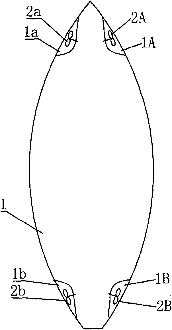
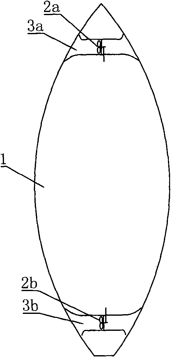
[0025] Such as figure 1 As shown, it is a schematic diagram of an embodiment of a flexible steering device for a ship. It is located on the front and rear sides of the hull 1, at a position below the waterline, and is provided with gradually concave streamlined grooves 1a, 1A, 1b, 1B. A propeller (or nozzle) is respectively housed in the interior, is respectively propeller 2a, 2A, 2b, 2B, and propeller structural form can adopt the propeller that the stern is used for the propeller that steamship advances. In this way, when the ship needs to turn to the right, one or both of the propellers 2a, 2B start or start simultaneously to produce a transverse thrust (and / or pulling force) that makes the hull 1 rotate to the right on the bow or stern, and when the propeller reverses to absorb water ), the moment couple formed by this thrust makes the hull quickly turn to the right. In the same way, when it is necessary to turn to the left, any one or both of the propellers 2b and 2A are...


PUM


Abstract

The invention discloses a flexible steering gear for steamships. The flexible steering gear is a propelling device which is arranged on bow and / or stern at a position below steamship waterline for generating lateral thrust on a hull. The flexible steering gear for steamships can realize quick steering of steamships, add a braking device, automatically match the use to improve flexibility of the steering gear, and is especially suitable for large steamships and battleships.

Description

technical field [0001] The invention relates to a flexible steering device for a ship, in particular to a device for quickly turning the ship by using lateral water spray or water absorption to generate lateral push and pull forces. Simultaneously also need deceleration braking device (original propeller reverse), or another propulsion device and the device that original propeller turns opposite. Background technique [0002] According to the traditional theory of mechanics, the forces in one-dimensional space, a single force, cannot be balanced. There must be another force before it can be balanced. The balance condition is: the balance condition of the two force balance is: equal in magnitude, opposite in direction, acting on the same straight line (rigid body), or acting on the same point on the same straight line (deformable body). [0003] Couple moment in two-dimensional space: extend the balance of force one step further, if the two balanced forces do not act on the...

Claims


Application Information

Patent Timeline
Patent Type & Authority Applications(China)
IPC IPC(8): B63H11/02B63H5/08
Inventor 徐国彬
Owner 徐国彬
Why Eureka
Try Eureka