Special oil filtering device for steam turbine capable of removing impurities and oil filtering method

An oil filter device and steam turbine technology, which is applied in separation methods, chemical instruments and methods, filtration and separation, etc., can solve the problem that the oil filter absorbs a lot of impurities, and achieve the effects of fast turning speed, stable performance, and reduced resistance

Pending Publication Date: 2019-05-24
大唐绥化热电有限公司
View PDF2 Cites 2 Cited by
  • Summary
  • Abstract
  • Description
  • Claims
  • Application Information

AI Technical Summary

Problems solved by technology

[0003] The filter oil of the steam turbine oil filter device currently used contains a lot of water and too much water vapor in the gas pumped out by the vacuum pump. In the vacuum pump, the vacuum oil is lower than the oil level line. Due to the use of After a long time, there will be a lot of water content, and the seals at the joints will leak, and the oil filter will absorb a lot of impurities.

Method used


Image

  • Special oil filtering device for steam turbine capable of removing impurities and oil filtering method
  • Special oil filtering device for steam turbine capable of removing impurities and oil filtering method

Examples


Embodiment 1

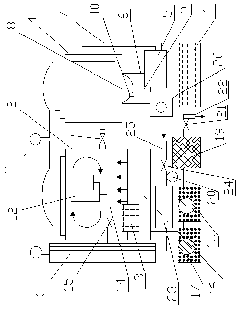
[0025] A special oil filter device for steam turbines capable of removing impurities, comprising: a water tank 1, a vacuum tank 2, a heater 3, a condenser 4 and a vacuum pump 5, the water tank is connected to the vacuum pump through a water pipe, and the The top of the vacuum pump is connected to the condenser through the inlet pipe 6, the side of the vacuum pump is connected to the condenser through the condenser outlet pipe 7, and the bottom of the condenser has a water storage tank 8. The bottom of the water storage tank is respectively connected with an exhaust pipe 9 and a drain pipe 10, and the top of the condenser is connected with the vacuum tank through a pipeline, and a vacuum gauge 11 is installed on the pipeline, and the water storage tank passes through the vacuum tank. The above air inlet pipe and the water outlet pipe of the condenser are combined with the condenser.

Embodiment 2

[0027] According to the special oil filter device for steam turbines that can remove impurities described in Embodiment 1, the vacuum tank has an atomizer 12 and a buoy 13, the bottom of the atomizer is connected to the nozzle 14, and the nozzle The pipe is connected with the heater, the nozzle is equipped with an automatic valve 15, the vacuum tank has an oil layer 16, and the buoy is arranged in the oil layer.

Embodiment 3

[0029] According to the special oil filtering device for steam turbines capable of removing impurities described in Embodiment 1 or 2, the bottom of the vacuum tank is connected to the propeller 17 through a pipeline, and the propeller is connected to the oil drain pump 18, and the drain The oil pump is connected to the fine filter 19 through a pipeline, and a pressure gauge 20 is installed on the pipeline, and the fine filter is connected to the oil outlet pipe 22 through a check valve 21 .


PUM


Abstract

The invention relates to a special oil filtering device for a steam turbine and an oil filtering method. The oil filtering device is mainly used for treating the turbine oil of a generator set and canquickly and effectively remove moisture, gas and impurities in the oil. The oil filtering device comprises a water tank (1), a vacuum tank (2), a heater (3), a condenser (4) and a vacuum pump (5), wherein the water tank is connected with the vacuum pump through a water pipe; the top of the vacuum pump is connected with the condenser through an air inlet pipe (6); the side surface of the vacuum pump is connected with the condenser through a condenser discharging pipe (7), the bottom of the condenser is provided with a water storage tank (8), the lower part of the water storage tank is connected with an air discharging pipe (9) and a water discharging pipe, the upper part of the condenser is connected with the vacuum tank through a pipeline, a vacuum meter (11) is arranged on the pipeline,the invention relates to the oil filtering device of the steam turbine.

Description

Technical field: [0001] The invention relates to a special oil filtering device and an oil filtering method for a steam turbine capable of removing impurities. Background technique: [0002] The oil filter device of the steam turbine is mainly used for the treatment of the turbine oil of the generator set, which can quickly and effectively remove the moisture, gas and impurities in the oil. Improve the quality of oil, ensure the normal operation of the unit adjustment and lubrication system, and extend the maintenance cycle of the unit. [0003] The currently used steam turbine oil filter device contains a lot of water in the filtered oil, and the gas pumped out by the vacuum pump contains too much water vapor. In the vacuum pump, the vacuum oil is lower than the oil level line. The device will absorb a lot of impurities. Invention content: [0004] The object of the present invention is to provide a special oil filter device and oil filter method for steam turbines capa...

Claims


Application Information

Patent Timeline
Patent Type & Authority Applications(China)
IPC IPC(8): B01D36/00
Inventor 郝雨光王永宏马金波闫清慧宋强熊健张云龙柳金池
Owner 大唐绥化热电有限公司
Why Eureka
Try Eureka