Metal coiled pipe fan assembly machine

A technology of pipe fan and assembly machine, which is applied in metal processing, machine/engine, metal processing equipment, etc.

Active Publication Date: 2011-02-09
宁波朗迪环境科技有限公司
View PDF0 Cites 3 Cited by
  • Summary
  • Abstract
  • Description
  • Claims
  • Application Information

AI Technical Summary

Problems solved by technology

[0003] The purpose of the invention is to solve the production and technical defects in the assembly of the existing metal coil fan, and provide a coil fan assembly machine with semi-automatic operation, high assembly efficiency, good product quality and low production cost

Method used


Image

  • Metal coiled pipe fan assembly machine
  • Metal coiled pipe fan assembly machine
  • Metal coiled pipe fan assembly machine

Examples


Embodiment 1

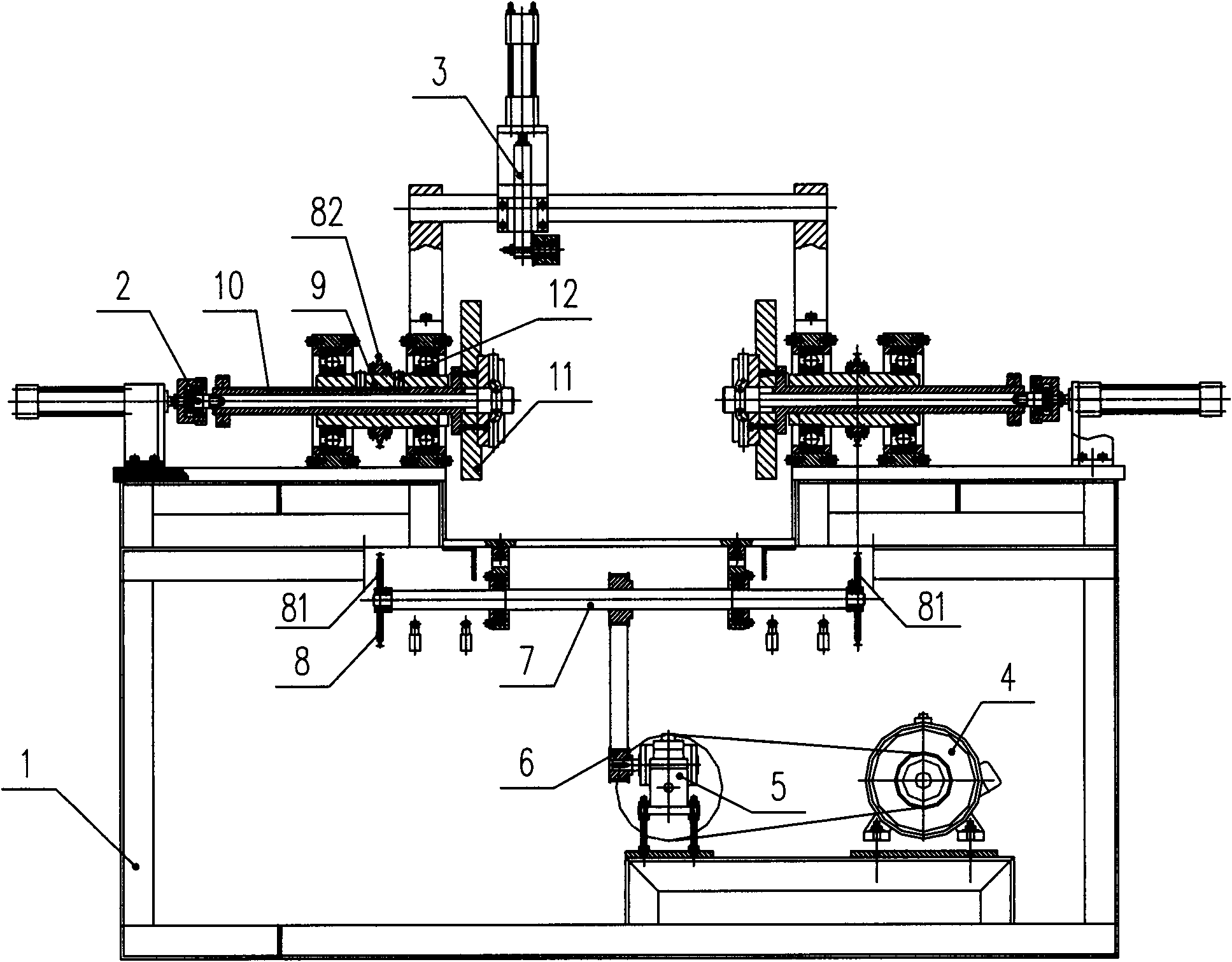
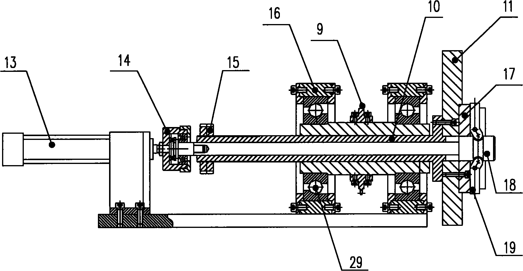
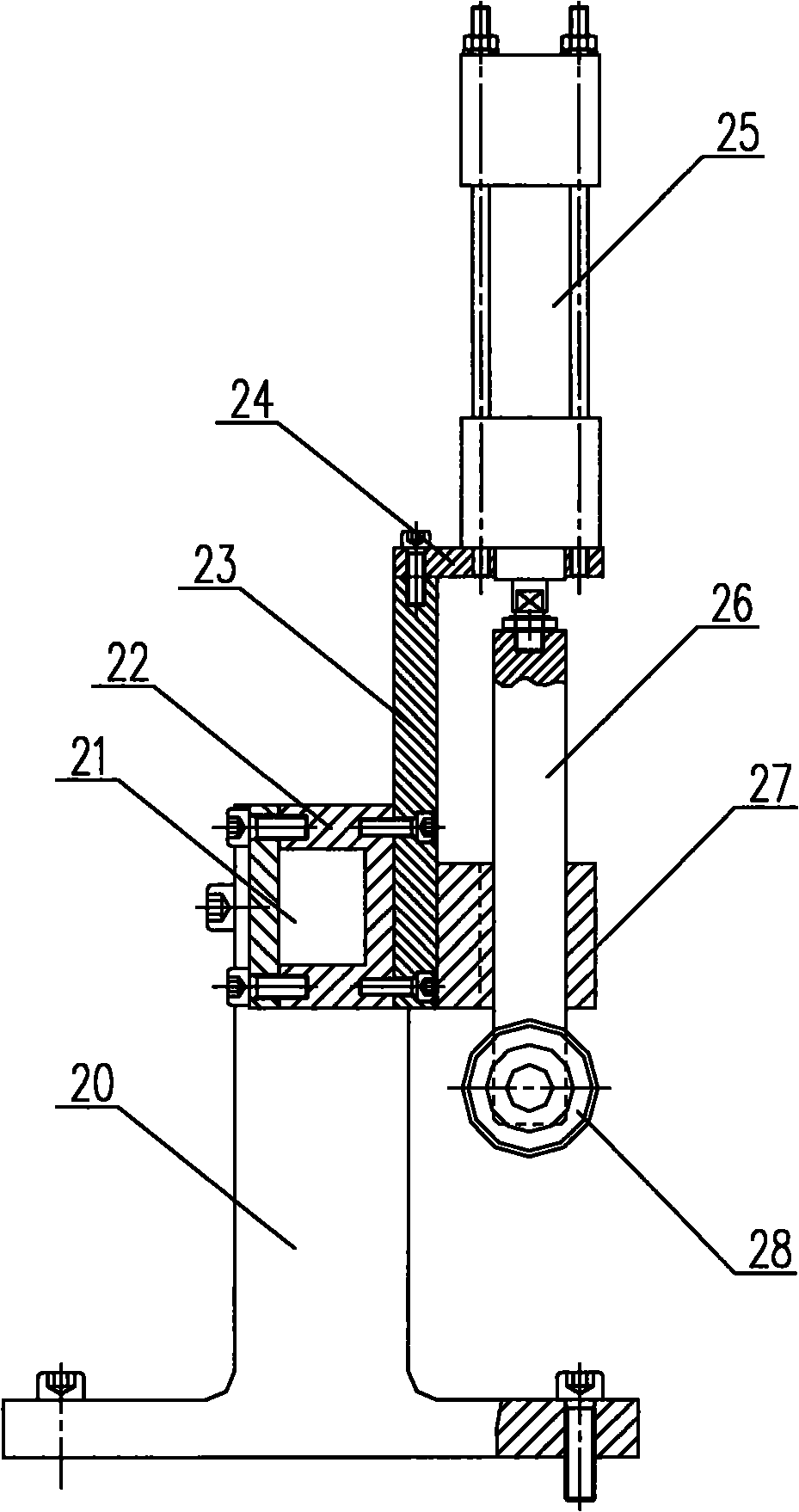
[0026] Such as Figure 1~3 The metal coil fan assembly machine shown is composed of a frame 1 , a bracket 20 installed on the frame, a transverse guide rail 21 , a power transmission mechanism, a side plate locking mechanism 2 and a shroud pressing mechanism 3 . The transverse guide rail 21 is mounted on the bracket 20 .

[0027] The power transmission mechanism consists of a motor 4, a reducer 5, a synchronous gear train 6, a transmission shaft 7 and a transmission device 8; the motor 4 is connected to the transmission shaft 7 through a reducer 5, and the output end of the reducer 5 to the transmission shaft 7 adopts a synchronous gear train 6 transmission, to achieve the relative accuracy of the halfway stop assembly position during operation, and the installation position will not change for a long time. The motor 4 and the reducer 5 are connected by a V-belt transmission, which acts as a shock absorber. The transmission device 8 is mounted on the transmission shaft 7 . ...

Embodiment 2

[0035] Such as Figure 2-4 The metal coil fan assembly machine shown is composed of a frame 1 , a bracket 20 installed on the frame, a transverse guide rail 21 , a power transmission mechanism, a side plate locking mechanism 2 and a shroud pressing mechanism 3 . The transverse guide rail 21 is mounted on the bracket 20 . The structures of the power transmission mechanism and the side plate locking mechanism 2 are the same as those described in Embodiment 1.

[0036] The coaming pressing mechanism 2 is left and right 2 groups, is all installed on the guide rail 21 and can move left and right, and the structure of each group is identical with that described in embodiment 1.

[0037] When in use, two groups of coaming pressing mechanisms on the left and right are used to press the two sides of the coaming respectively. If there is a difference in height between the two sides of the coaming, it will not appear that one side can be compressed but the other cannot be pressed tightl...


PUM


Abstract

The invention relates to a metal coiled pipe fan assembly device. A metal coiled pipe fan assembly machine comprises a stander, and a bracket, a transverse guide rail, a power transmission mechanism, a lateral plate locking mechanism and an enclosure plate pressing mechanism which are mounted on the stander. The transverse guide rail is mounted on the bracket. The metal coiled pipe fan assembly machine has the advantages of high production efficiency, high assembly quality, low product rejection rate, reduction of production cost, good service performance and high automatization degree.

Description

technical field [0001] The invention relates to an assembly equipment of a metal coil fan. Background technique [0002] Metal coil fans are assembled from fan blades and matching volutes. The volute includes: left side plate, right side plate and surrounding plate. The existing assembly method adopts full manual operation. An operator fixes the hoarding board, the left side board and the right side board in the shape of a semi-circular barrel by hand. Another operator attached it with self-tapping screws using a pneumatic screwdriver. The self-tapping screws at the air outlet end are not installed and transferred to the next process. Put the fan blades from the air outlet end into the volute, and then tighten the self-tapping screws at the air outlet. The coil fan after manual assembly must be reshaped, and four people operate to complete the assembly of a fan. Defects in the existing assembly process: 1. Too much labor and low production efficiency; 2. Difficult to co...

Claims


Application Information

Patent Timeline
Patent Type & Authority Patents(China)
IPC IPC(8): B23P19/04F04D29/60
Inventor 高炎康黄其全
Owner 宁波朗迪环境科技有限公司
Why Eureka
Try Eureka