High-current self-clean cam switch

A cam switch, self-cleaning technology, applied in the direction of contact meshing, contact drive mechanism, etc., can solve problems such as difficulty in adapting to high current, cam switch does not have self-cleaning function, etc., to achieve the effect of wide application

Inactive Publication Date: 2010-03-17
SHANGHAI ELECTRICIAN IND & COMMERCE +1
View PDF0 Cites 2 Cited by
  • Summary
  • Abstract
  • Description
  • Claims
  • Application Information

AI Technical Summary

Problems solved by technology

[0006] The technical problem to be solved by the present invention is to provide a cam switch that can be widely used in large, medium and small currents for the problems that the commonly used cam switches do not have self-cleaning function and the existing self-cleaning cam switches are difficult to adapt to large currents. self-cleaning cam switch

Method used


Image

  • High-current self-clean cam switch
  • High-current self-clean cam switch
  • High-current self-clean cam switch

Examples


Embodiment Construction

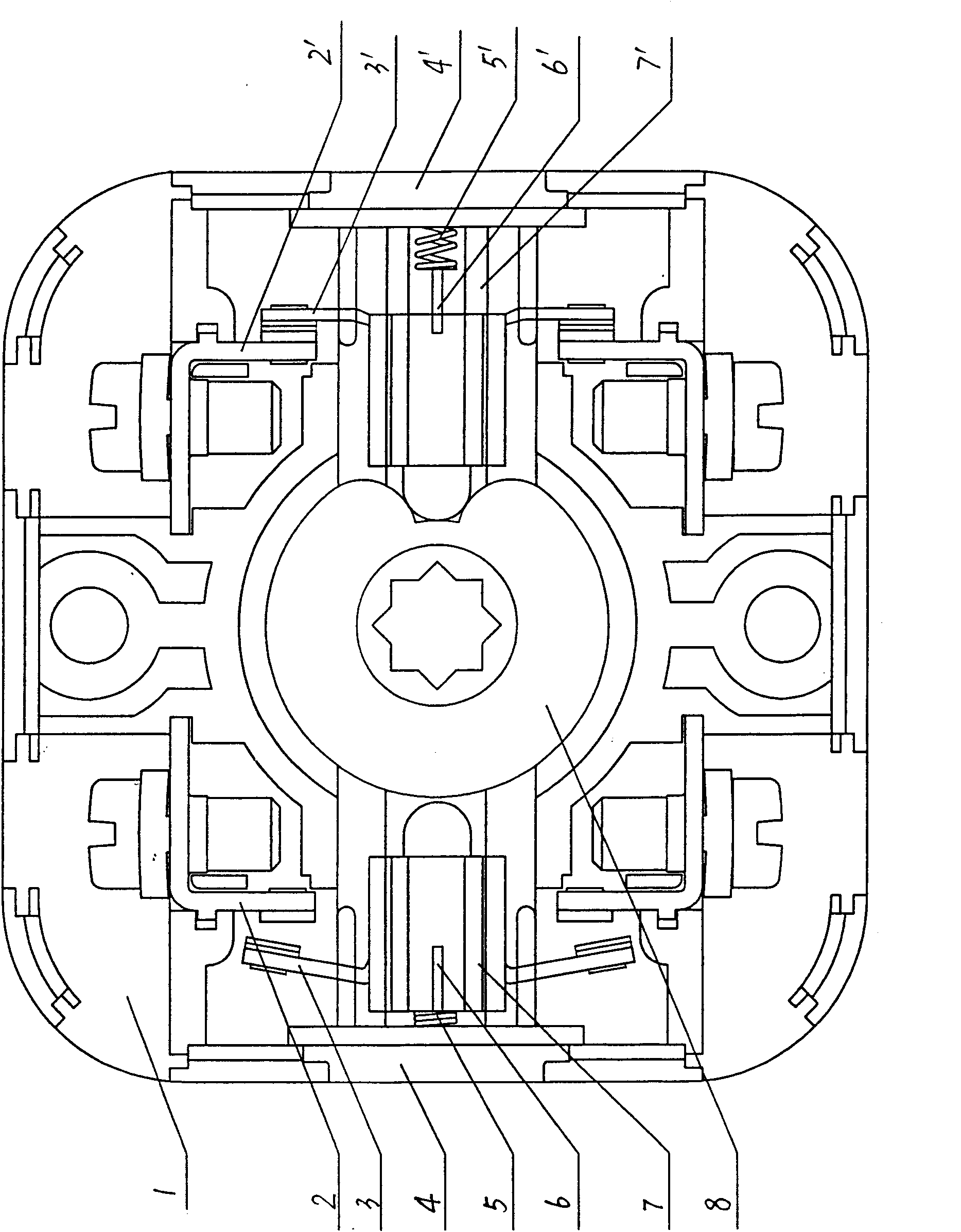
[0021] Such as figure 1 , figure 2 and image 3 as shown,

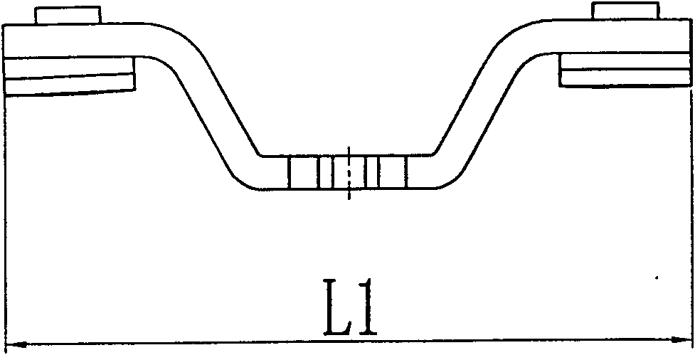
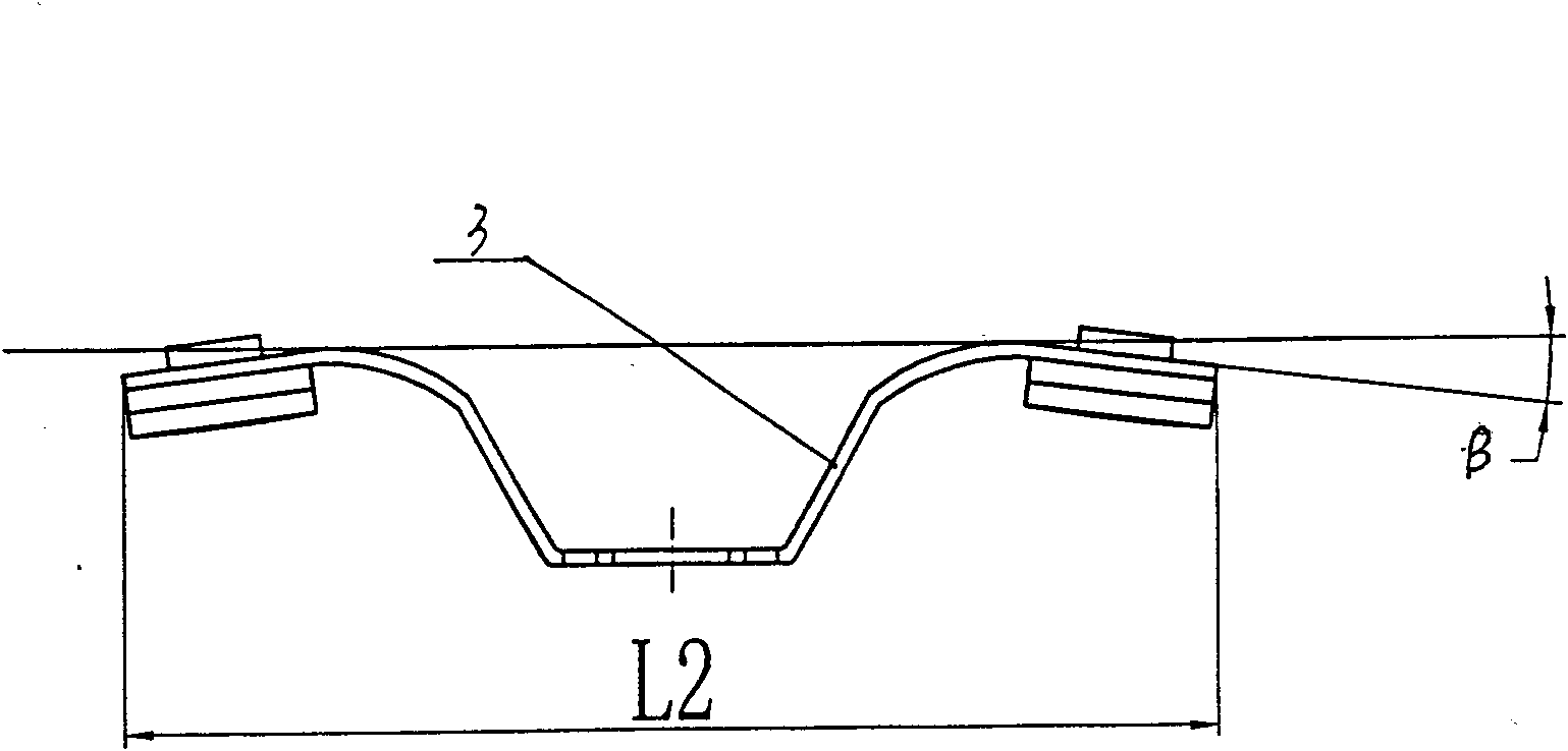
[0022] A high-current self-cleaning cam switch, comprising a contact base 1, a round hole is opened in the middle of the contact base 1, a cam 8 is arranged in the round hole, static contacts 2, 2', the two sides of the cam 8 are respectively provided with a bracket 7, 7', and a moving contact 3, 3' with a double contact is installed on the bracket 7, 7', and the moving contact 3 corresponds to the static contact 2, The moving contact 3' corresponds to the static contact 2', a pair of spring seats 4, 4' are arranged on both sides of the contact base 1, and a pair of spring seats 4, 4' are provided between the moving contacts 3, 3' and the spring seats 4, 4' The springs 5, 5' are compressed, and the contacts on both sides of the movable contacts 3, 3' are inclined to the direction of the cam 8 by an angle β, image 3 The length of the moving contact 3, 3' in is L2, figure 2 The length of the standard moving cont...


PUM


Abstract

The invention discloses a high-current self-clean cam switch, which comprises a contact substrate of which the middle is provided with a round hole; a cam is arranged in the round hole; a pair of static contacts is symmetrically arranged on two sides of the contact substrate; two lateral surfaces of the cam are oppositely provided with supports; the supports are assembled with a dual-contact pointmoving contact respectively; the moving contacts respectively correspond to the static contacts; compression springs are arranged between the moving contacts and the side wall of the contact substrate; contact points on two sides of each moving contact are inclined an angle toward the cam direction; the length of the moving contacts is slightly greater than a standard length; and the moving contacts are made of an elastic material. Aiming at the problems that the commonly used cam switch does not have self-clean function and the prior self-clean cam switch is difficult to adapt to high current, the invention provides the self-clean cam switch capable of being widely suitable for high, intermediate and low current, which can automatically remove impurities such as dust and the like, does not easily have poor contact, and can be widely suitable for controlling the high, intermediate and low current.

Description

technical field [0001] The invention relates to a cam switch, in particular to a self-cleaning cam switch. Background technique [0002] Cam switch refers to an electrical appliance that adjusts and controls the working state of contacts through cam movement. At present, the commonly used cam switch is equipped with a double-contact contact on the bracket on the side of the cam, and a compression spring is arranged between the contact and the side wall of the contact base. When the cam rotates, the bracket moves with the cam to drive the movement of the contacts, thereby realizing the disconnection and connection of the contacts. When the support is at the concave point of the cam, the switch is in the on state, and when the support is at the salient point of the cam, the switch is in the off state. This structure has two disadvantages: 1. The breaking rate of the contact is affected by the shape of the cam, so it cannot reach a relatively high breaking rate, which is easy...

Claims


Application Information

Patent Timeline
Patent Type & Authority Applications(China)
IPC IPC(8): H01H3/42H01H1/36
Inventor 陈小萍王海燕
Owner SHANGHAI ELECTRICIAN IND & COMMERCE
Why Eureka
Try Eureka