Damping device for elevator and elevator employing the same
A vibration damping device and elevator technology, which is applied in the field of elevators and can solve problems such as increasing the load mass, increasing the weight of the car, and increasing the number of ropes
- Summary
- Abstract
- Description
- Claims
- Application Information
AI Technical Summary
Problems solved by technology
Method used
Image

Examples
no. 1 approach
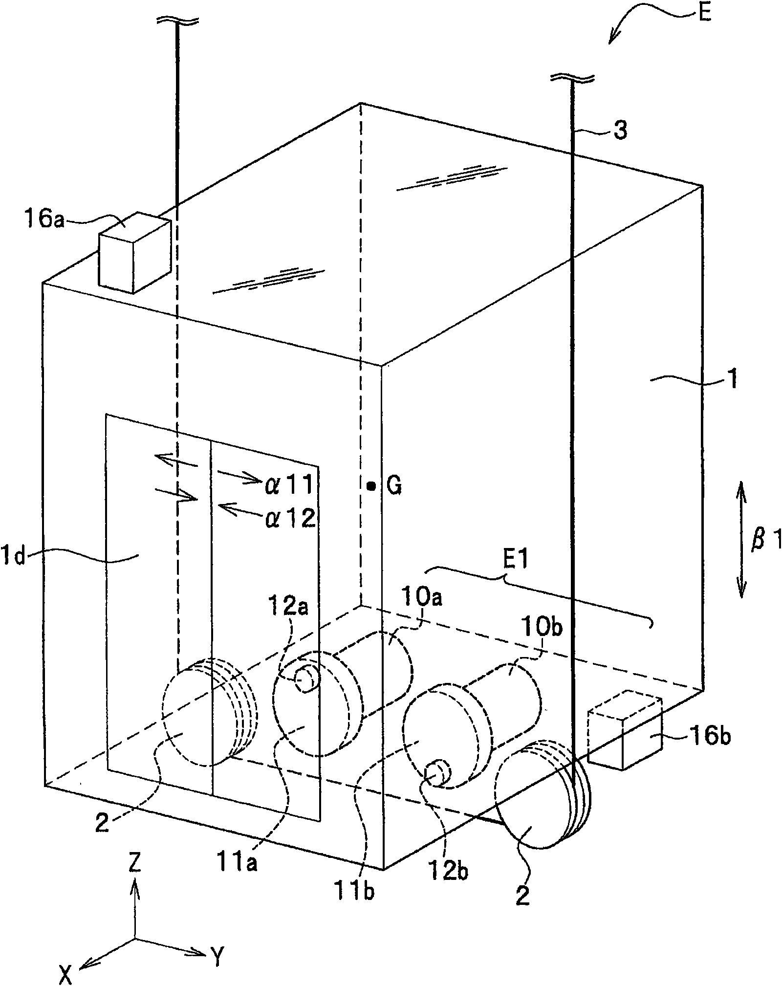
[0025] figure 1 It is a perspective view showing the elevator E of the first embodiment of the present invention.
[0026] (Overall structure of elevator E)
[0027] Such as figure 1 As shown, the elevator E of the first embodiment is equipped with: a car 1, which conveys people entering the elevator from a door 1d, and the door 1d is opened and closed when a person enters or exits the elevator (refer to figure 1 Arrows α11, α12 of arrows α11 and α12); pulley 2, which is rotatably installed on the lower part of the car 1; hoisting rope 3, which is wound and hung on the pulley 2, and the pulley 2 is rotated by winding up or down, Thereby making the car 1 lift ( figure 1 arrow in the direction of β1).
[0028] Such as figure 1 As shown, the center of gravity G of the car 1 is located in the approximate center of the car 1 .
[0029] In the following description, the side of the car 1 of the elevator E having the door 1d is taken as the front, the depth direction is taken a...
no. 2 approach
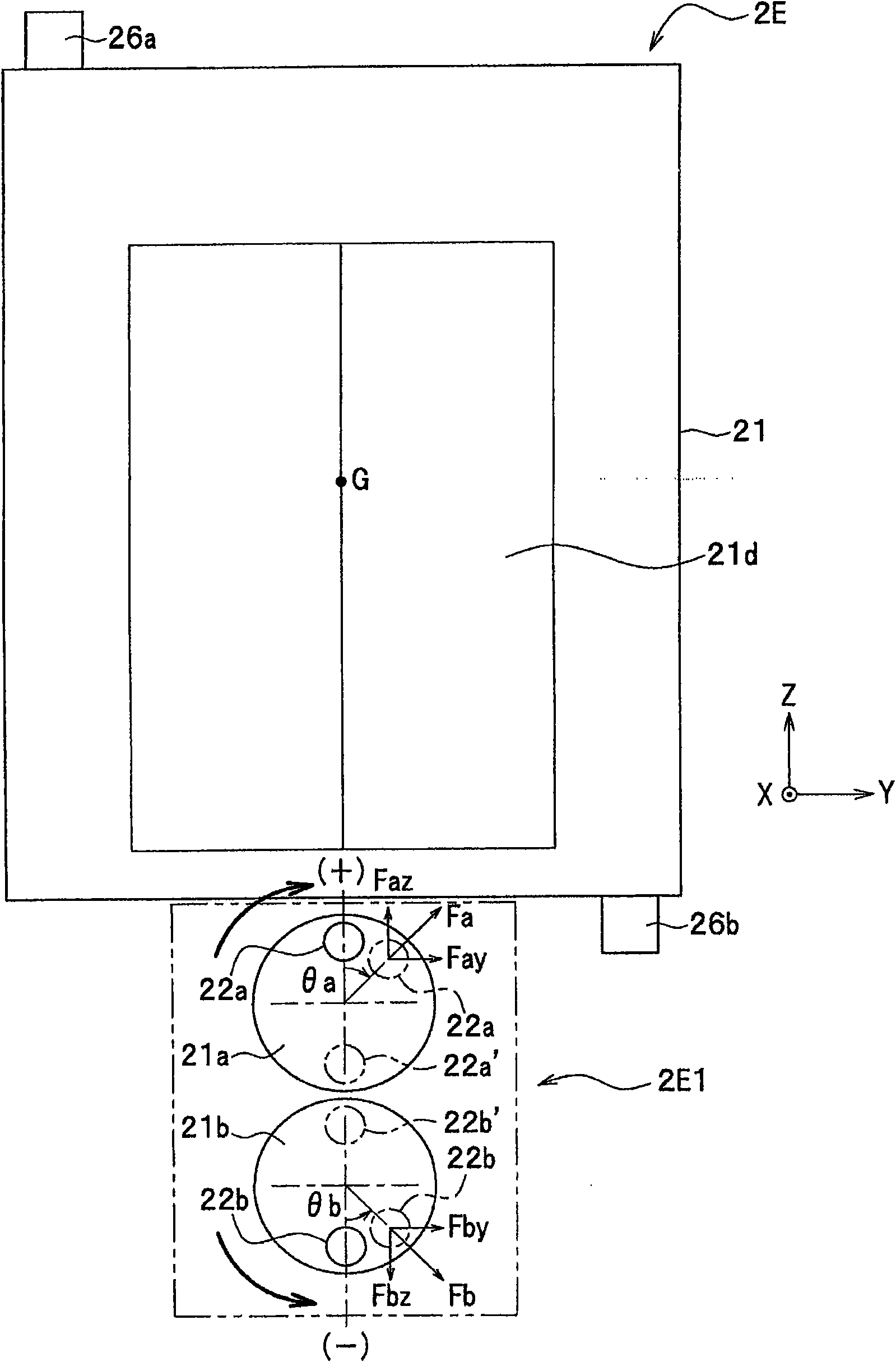
[0062] Next, use image 3 An elevator 2E according to a second embodiment of the present invention will be described.
[0063] image 3 It is a front view which shows the elevator 2E of 2nd Embodiment.
[0064] image 3 The vibration damping device 2E1 of the elevator 2E according to the second embodiment shown has a set of hammers 22a, 22b arranged vertically above and below in order to damp the lateral vibration of the car 21 in the Y direction (horizontal direction).
[0065] The vibration damping device 2E1 has a vibration damping effect on the translational motion of the car 21 in the Y direction and a vibration damping effect on the rotational motion of the car 21 around the X axis.
[0066] The structure other than that is the same as that of the first embodiment, and therefore the same structural elements are assigned the symbols of the 20th paragraph, and detailed description thereof will be omitted.
[0067] Such as image 3 As shown, the rotating plate 21a and ...
no. 3 approach
[0082] Next, use Figure 5 The elevator 3E of 3rd Embodiment is demonstrated.
[0083] Figure 5 It is the top view which looked at the elevator 3E of 3rd Embodiment from above.
[0084] Figure 5 The car 31 shown consists of a Figure 5 The guide rails g31 and g32 extending in the direction of the front and back of the paper are guided along the Figure 5 The direction of the front and back of the paper is raised and lowered.
[0085] exist Figure 5 In the elevator 3E according to the third embodiment shown, in order to damp the vibration of the car 31 in the X direction (depth direction), the disks 31a and 31b of the vibration damping device 3E1 are directed upward below the car 31. And horizontally arrange the vibration damping device 3E1 parallel to the XY plane.
[0086] The hammer 32a fixed to the circular plate 31a and the hammer 32b fixed to the circular plate 31b of the vibration damping device 3E1 are the same as those of the first and second embodiments, and...
PUM
 Abstract
Description
Claims
Application Information