Vacuum pump

A technology for vacuum pumps and substrates, applied in pumps, pump components, rotary piston pumps, etc., can solve problems such as poor heat dissipation and high noise, and achieve the effects of slowing down the airflow speed, reducing noise, and facilitating heat dissipation

Active Publication Date: 2010-03-24
BYD CO LTD
View PDF1 Cites 32 Cited by
  • Summary
  • Abstract
  • Description
  • Claims
  • Application Information

AI Technical Summary

Problems solved by technology

[0006] The purpose of the present invention is to overcome the defects of the existing vacuum pumps such as high noise and poor heat dissipation effect, and provide a vacuum pump that can reduce noise and have good heat dissipation effect.

Method used


Image

  • Vacuum pump
  • Vacuum pump
  • Vacuum pump

Examples


Embodiment Construction

[0012] Specific embodiments of the present invention will be described in detail below with reference to the accompanying drawings.

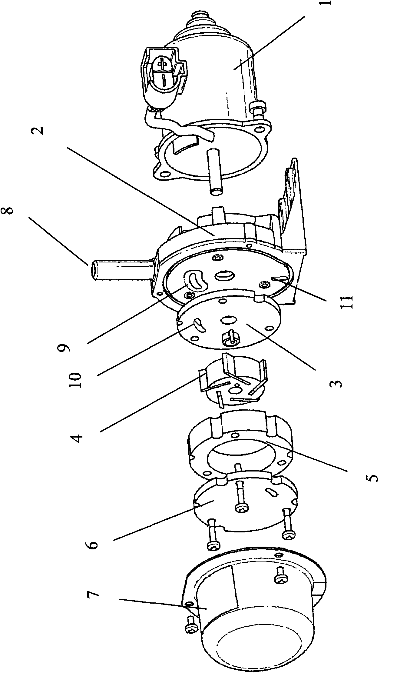
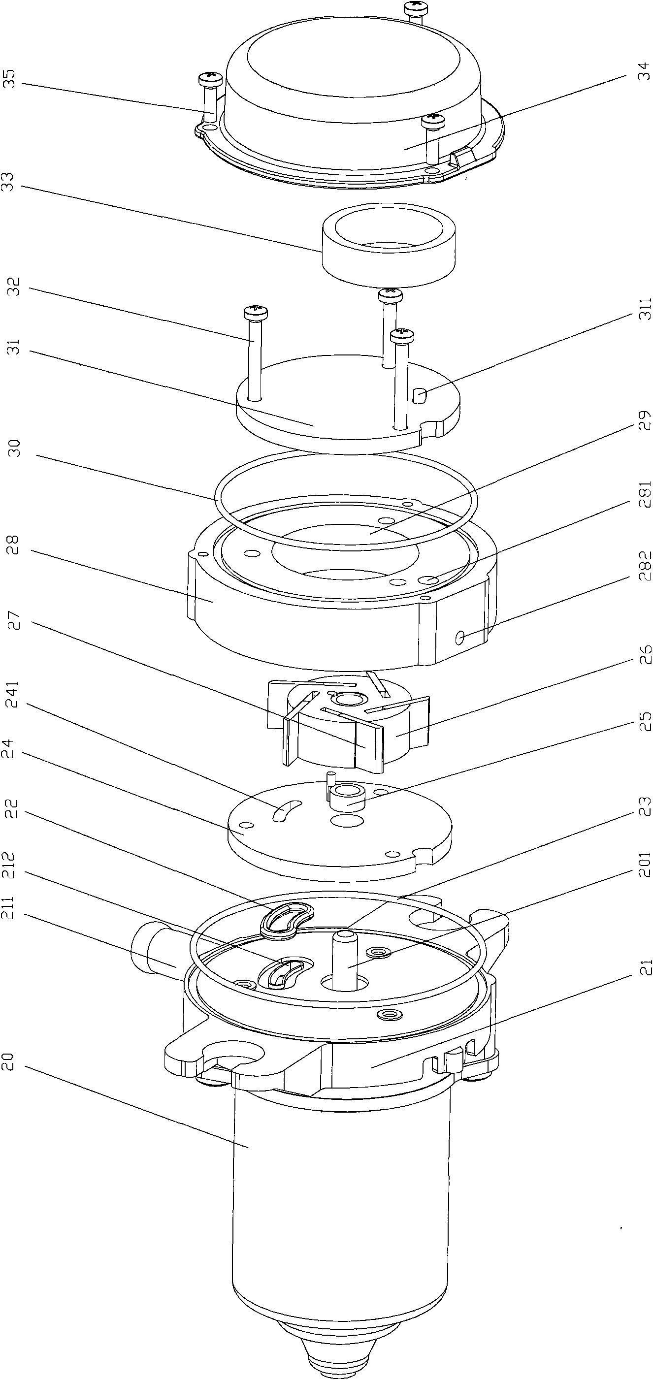
[0013] Before going into details, it should first be explained that, unless otherwise specified, the "upper end" mentioned in the claims and description of the present invention refers to the side close to the first substrate along the axial direction of the mount ( which is figure 2 The end of the upper side), the "lower end" refers to the side close to the driver along the axial direction of the mounting seat (ie figure 2 The end of the lower side), similarly, the "upper" and "lower" mentioned in the claims and description of the present invention refer to figure 2 The upper and lower sides are shown for ease of description.

[0014] Such as figure 2 As shown, a vacuum pump is provided according to an embodiment of the present invention, and the vacuum pump includes:

[0015] a drive 20 with a drive shaft 201;

[0016] The mounting ba...


PUM


Abstract

The invention relates to a vacuum pump which comprises a driver, a mounting base, a first substrate, a rotor, a pump ring, a second substrate and a cover. The driver is provided with a driving shaft and is arranged on the lower side of the mounting base; the mounting base is provided with an air inlet hole and a first through hole which are communicated with each other; the first substrate is provided with a second through hole; the rotor is provided with blades; the second substrate is provided with a third through hole; the driving shaft penetrates through the first substrate and is matchedwith a rotor which is arranged in a hollow cavity formed by the first substrate, the pump ring and the second substrate; the first through hole, the second through hole and the hollow cavity are communicated with the third through hole; and the cover, the second substrate, the pump ring and the first substrate are assembled on the upper side of the mounting base through mounting bolts. The vacuumpump also comprises a silencing ring which forms a first chamber and a second chamber which are communicated with each other. The pump ring is provided with an air outlet through hole and an air outlet hole which are communicated with each other; the first chamber is communicated with the hollow cavity; and the second chamber is communicated with the air outlet hole. The vacuum pump of the invention has the advantages of noise reduction and good radiating effect.

Description

technical field [0001] The invention relates to a vacuum pump. Background technique [0002] A vacuum pump is a device that uses mechanical or physical methods to pump air into a container or a closed chamber to obtain and maintain a certain degree of vacuum. Vacuum pumps are often combined with vacuum containers, vacuum valves, vacuum measuring instruments, pipelines and other devices to form a vacuum system, which is widely used in various industrial fields. [0003] According to the working principle, vacuum pumps can be divided into two types: gas delivery pumps and gas capture pumps. Among them, gas delivery pumps generally include liquid ring vacuum pumps, reciprocating vacuum pumps, and rotary vane vacuum pumps; gas capture pumps generally include adsorption pumps and cryogenic pumps. However, due to the advantages of high vacuum degree and compact structure, the rotary vane vacuum pump is widely used in the industry at present. [0004] US6491505B1 discloses a kin...

Claims


Application Information

Patent Timeline
Patent Type & Authority Applications(China)
IPC IPC(8): F04C18/344F04C25/00F04C29/04F04C29/06
CPCF04C2220/10F04C29/068F04C29/04F04C29/065F04C27/005F04C18/3442
Inventor 赵兵袁野陈淑君唐振林
Owner BYD CO LTD
Why Eureka
Try Eureka