Intraocular lens injector

A technology of injector and main body, applied in the field of intraocular lens injector, can solve the problems of increasing IOL damage and the like

Inactive Publication Date: 2010-03-24
BAUSCH & LOMB INC
View PDF0 Cites 9 Cited by
  • Summary
  • Abstract
  • Description
  • Claims
  • Application Information

AI Technical Summary

Problems solved by technology

Bending may be especially pronounced when the lens passes through the funnel-shaped portion of the lumen and is being compressed, which may increase the likelihood of IOL damage during delivery

Method used


Image

  • Intraocular lens injector
  • Intraocular lens injector
  • Intraocular lens injector

Examples


Embodiment Construction

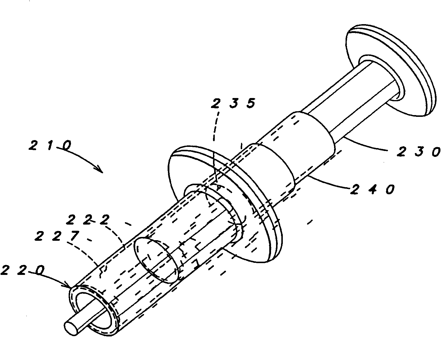
[0022] Figure 2A is a schematic view of an example embodiment of an IOL injector 210 according to aspects of the present invention; and Figure 2B is a cross-sectional view of an embodiment of an IOL syringe. IOL syringe 210 includes a syringe body 220, a plunger 230, and a sleeve 240 having a length L. As shown in FIG. A sleeve 240 is disposed between at least a portion of the plunger and at least a portion of the syringe body. Piston 230 is shown fully retracted. Nozzles and IOLs (as shown in Figures 1A and 1B) were placed in Figure 2A and 2B in and in the figures discussed below to avoid confusion. It should be understood that the syringe shown in any of the Figures may include a nozzle of any suitable configuration having an orifice for delivering the IOL into the eye.

[0023] The syringe body 220 has a lumen wall 222 defining a lumen 227 . Piston 230 is configured and arranged to move through the lumen. The wall may completely enclose the lumen along its entire l...


PUM


Abstract

An IOL injector (210), comprising an injector body (220) having a lumen wall (222) defining a lumen (227), a plunger (230) configured and arranged to move through the lumen, and a sleeve (240), the sleeve configured and arranged so as to contact at least a portion of the lumen wall and to slidably engage with at least a portion of the plunger.

Description

technical field [0001] The present invention relates to an intraocular lens (IOL) injector, and more particularly to an IOL injector providing piston control. Background technique [0002] An IOL is an artificial lens used to replace or supplement a patient's natural lens when the patient's natural lens is diseased or damaged. The IOL can be placed in the posterior or anterior chamber of the eye. IOLs come in a variety of structures and materials. [0003] Various instruments and methods are known for implanting such IOLs in the eye. Typically, an incision is made in the patient's cornea, and an IOL is implanted into the eye through the incision. In one technique, the surgeon grasps the IOL with surgical forceps and implants it through an incision into the eye. While the technology is still in use today, more and more surgeons are using IOL injectors, with advantages such as giving the surgeon more control when implanting the IOL in the eye and allowing the IOL to be pas...

Claims


Application Information

Patent Timeline
Patent Type & Authority Applications(China)
IPC IPC(8): A61F2/16
CPCA61M5/31505A61F2/1662A61F2/167A61F2/16A61F9/007
Inventor B·D·拉特尔特
Owner BAUSCH & LOMB INC
Why Eureka
Try Eureka