Knitting method for tubular knitted fabric and tubular knitted fabric

A knitted fabric, tubular technology, applied in the field of knitting of tubular knitted fabrics

Inactive Publication Date: 2010-03-24
SHIMA SEIKI MFG LTD
View PDF2 Cites 12 Cited by
  • Summary
  • Abstract
  • Description
  • Claims
  • Application Information

AI Technical Summary

Problems solved by technology

Therefore, it is difficult to effectively shrink the belt-shaped sheet in its winding direction

Method used


Image

  • Knitting method for tubular knitted fabric and tubular knitted fabric
  • Knitting method for tubular knitted fabric and tubular knitted fabric
  • Knitting method for tubular knitted fabric and tubular knitted fabric

Examples


Embodiment approach 1

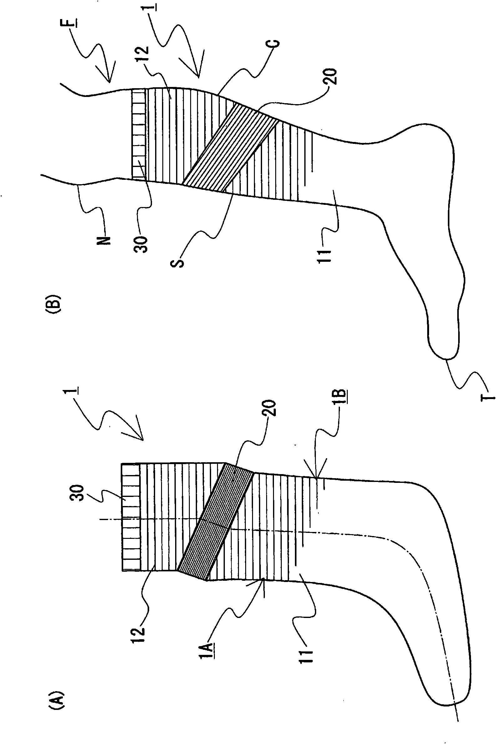
[0048] figure 1 (A) is a plan view of the sock, which is seen from the side corresponding to the position of the ankle during wearing. in addition, figure 1 (B) is a schematic diagram of a state of wearing socks seen from the ankle side.

[0049] As shown in the two figures, the sock 1 has: a lower knitted portion 11 covering the halfway from the toe T of the wearer’s foot F to the calf C and the calf S; an upper knitted portion 12 covering the calf C and the lower leg S; The upper part of the lower leg S; the ring-shaped elastic knitted part 20, which is arranged between these knitted parts 11, 12. The lower knit portion 11 corresponds to the first base knit portion, and the upper knit portion 12 corresponds to the second base knit portion.

[0050]Such as figure 1 As shown in (A), the elastic knit portion 20 does not extend coaxially with the lower knit portion 11 and the upper knit portion 12 , but is provided in an inclined axial direction with respect to the axial dir...

Embodiment 1

[0067] [Modification of Embodiment 1]

[0068] As a modified example of Embodiment 1, a method of knitting a tubular knitted product in which the direction in which the elastic knit portion extends obliquely is changed in the nail side knit portion and the back side knit portion will be described.

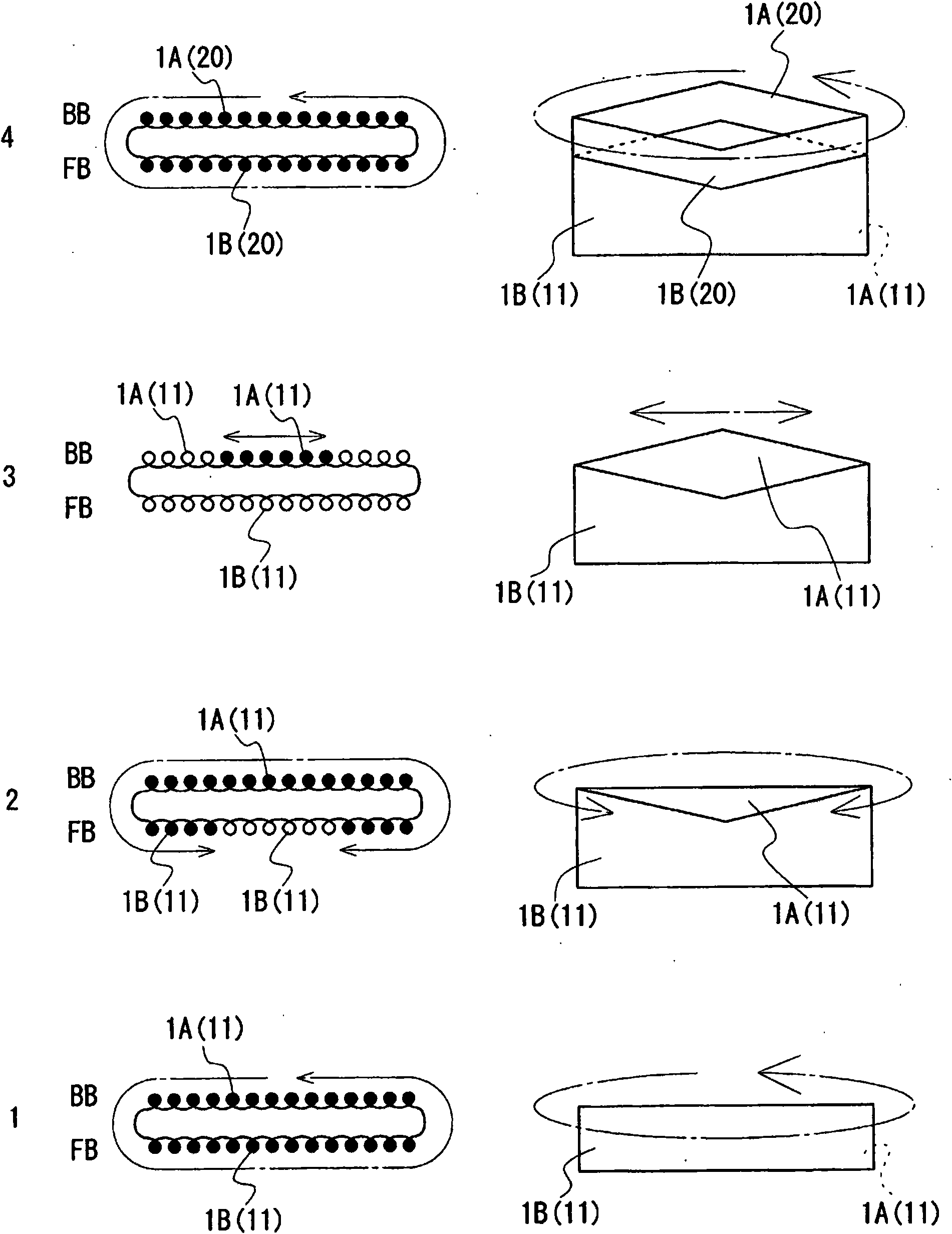
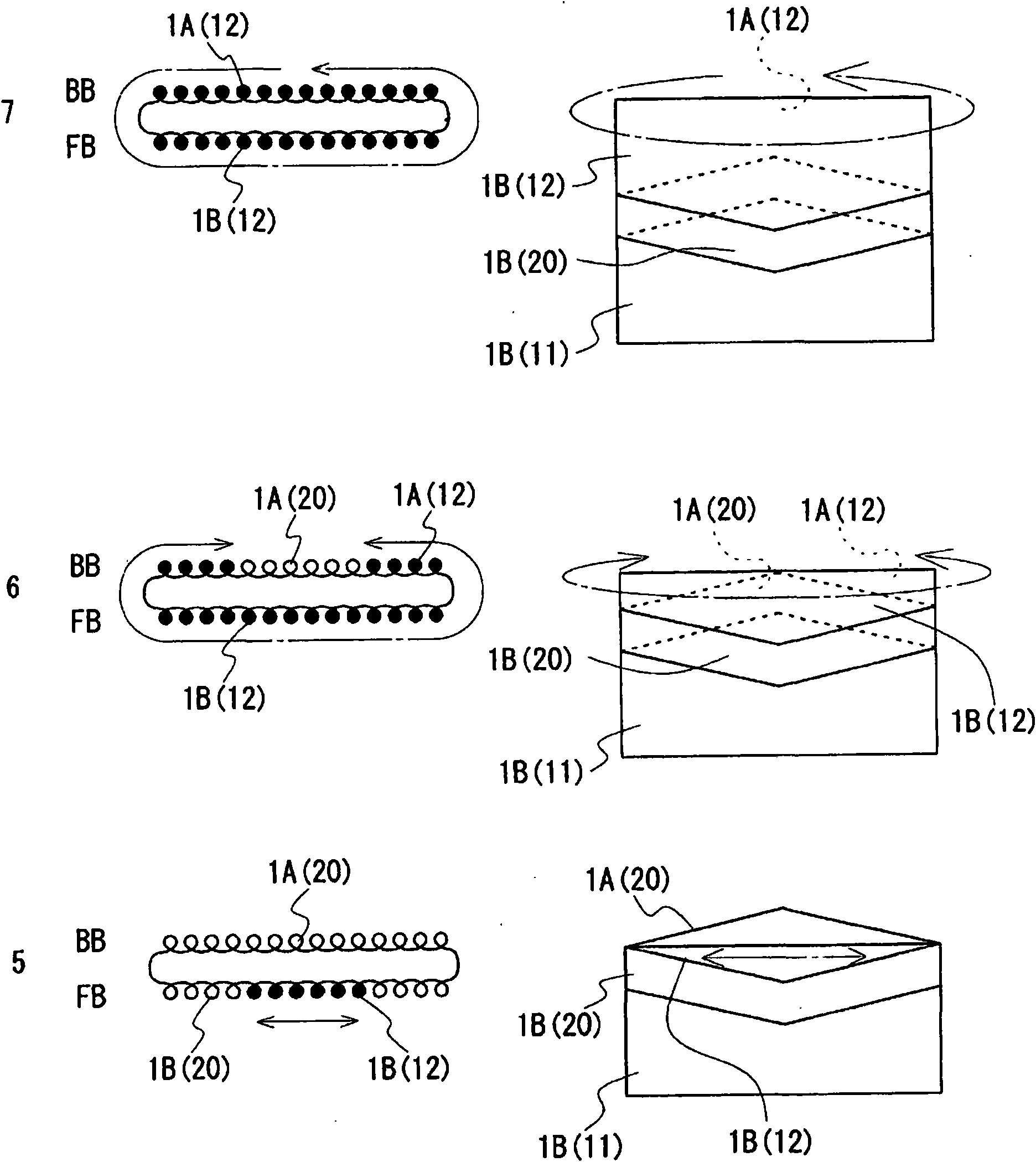
[0069] First, a method of knitting a sock in which the elastic knit portion forms a mountain shape when viewed from the ankle side, that is, a sock in which the elastic knit portion forms a valley shape when the sock is viewed from the front will be described. When knitting the elastic knit part of Yamagata, in figure 2 In step 2 of , similarly to the back side knitted portion 1B, the nail side knitted portion 1A also reduces stitches from the center of the knitted fabric to form the lower side knitted portion 11 . Furthermore, similarly to Embodiment 1, an elastic knit part 20 having the same number of stitches in each seaming direction is formed continuously to the lower side k...

Embodiment approach 2

[0072] In Embodiment 2, it is explained that it is possible to alleviate figure 1 The illustrated method of knitting the tubular knitted fabric of the steps formed between the lower knit part 11 and the elastic knit part 20 and between the elastic knit part 20 and the upper knit part 12 in the sock 1 is shown.

[0073] Figure 4 It is a figure which shows the sock 1 of this Example, Figure 4 (A) is a plan view of the sock 1, Figure 4 (B) is a schematic diagram showing a state in which the socks 2 are worn. Additionally, for and figure 1 The same configurations are denoted by the same symbols, and descriptions thereof are omitted.

[0074] The sock 1 of the present embodiment has a flat portion 210 at the middle portion of the nail side knit portion 1A and the middle portion of the back side knit portion 1B at the position of the elastic knit portion 21 . The flat portion 210 is a portion substantially parallel to the course direction of the lower knitted portion 11 . T...


PUM


Abstract

A tubular knitted fabric with annular obliquely arranged elastic knitted fabric area that ensures effective shrinkage along the circling direction of the elastic knitted fabric area; and a knitting method for the tubular knitted fabric. The tubular knitted fabric is obtained by knitting with the use of a flat knitting machine equipped with at least a pair of needlebeds extending in a horizontal direction and facing each other in an anteroposterior direction. The tubular knitted fabric comprises an annular elastic knitted fabric area (20) provided in a direction sloping with respect to the axial direction of the tubular knitted fabric; a first base knitted fabric area (11) coupled to a knitted stitch line appearing on a one edge side in the axial direction of the elastic knitted fabric area(20); and a second base knitted fabric area (12) coupled to a knitted stitch line appearing on the other edge side in the axial direction of the elastic knitted fabric area (20). The elastic knittedfabric area (20) has a course along the circling direction thereof.

Description

technical field [0001] The present invention relates to a knitting method of tubular knitted fabric and tubular knitted fabric. In particular, it relates to a method of knitting a tubular knitted fabric in which the winding direction of a ring-shaped elastic knitted portion is oblique to that of another knitted portion and the elastic knitted portion can be effectively shrunk in the winding direction. Background technique [0002] As a tubular knitted fabric having an annular elastic knitted portion, there is a sock described in Patent Document 1. In this sock, an elastic knitted portion parallel to the winding direction of the same knitted fabric is formed in the middle of the tubular knitted fabric. [0003] In addition, Patent Document 2 discloses a protector or stockings in which a helical belt-shaped piece is formed on a part of the tubular knitted fabric, and the belt-shaped piece has a higher tightening force than other parts. [0004] Patent Document 1: (Japanese) ...

Claims


Application Information

Patent Timeline
Patent Type & Authority Applications(China)
IPC IPC(8): D04B1/22D04B1/26
CPCD04B1/18D04B1/26D04B1/108D04B1/22
Inventor 弓场功雄
Owner SHIMA SEIKI MFG LTD
Why Eureka
Try Eureka