
Air pillow flow guidance and acoustic countermeasure system for an air intake tract

Inactive Publication Date: 2011-06-16
MANN HUMMEL GMBH
View PDF13 Cites 8 Cited by
  • Summary
  • Abstract
  • Description
  • Claims
  • Application Information

AI Technical Summary

Benefits of technology

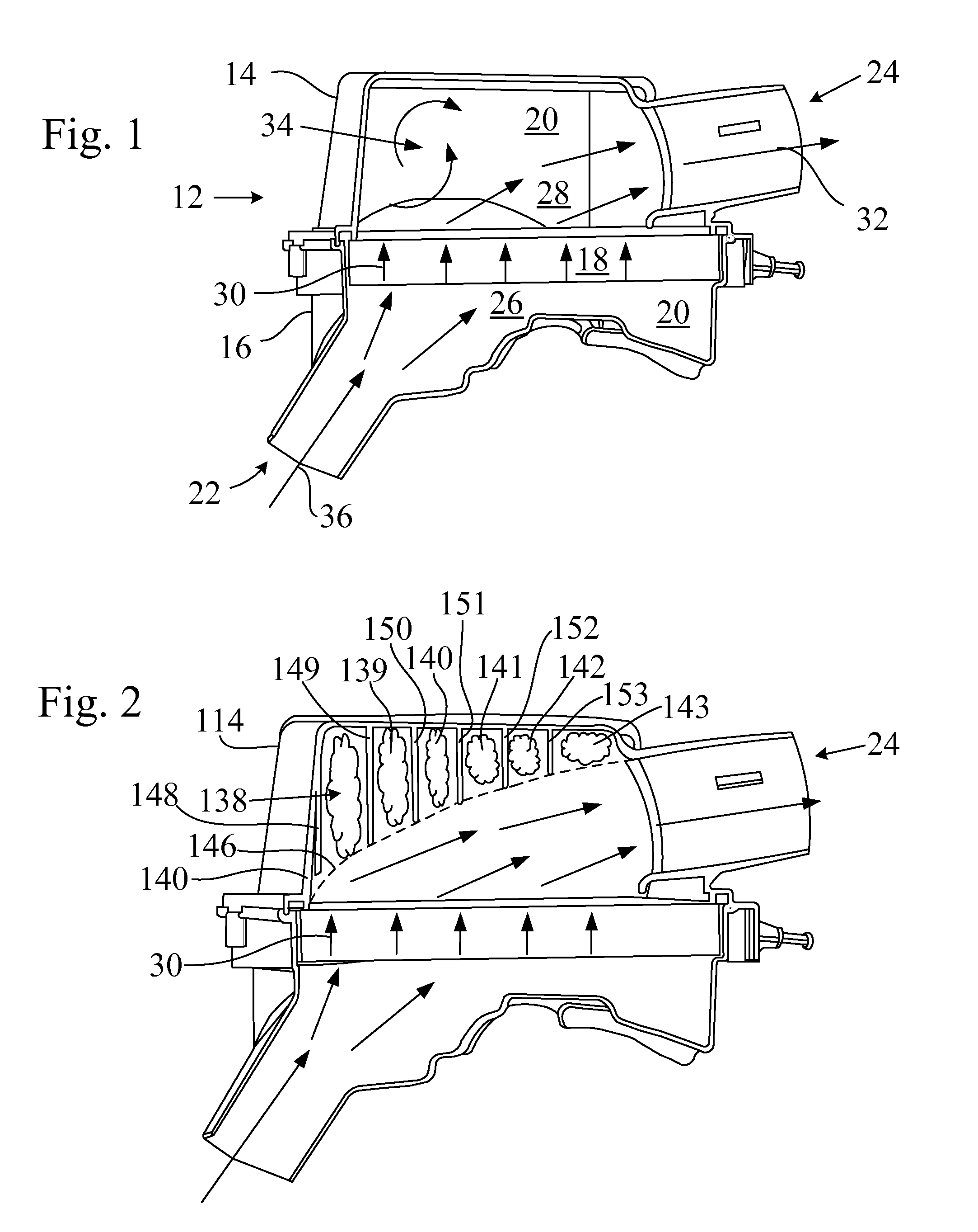
[0011]It is an object of the present invention is to reduce the pressure drop or flow restriction through an air induction system by reducing kinetic energy consuming air recirculation patterns and air turbulence in the air induction system.
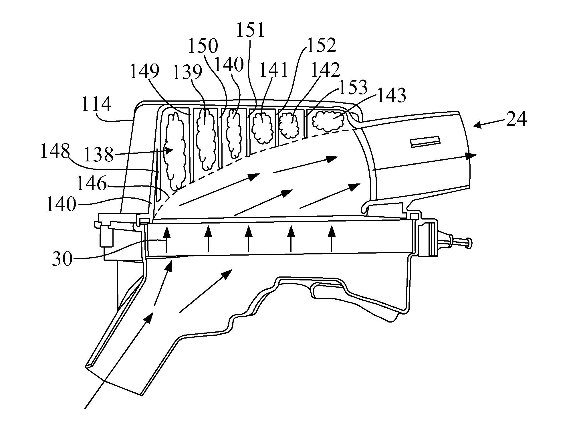
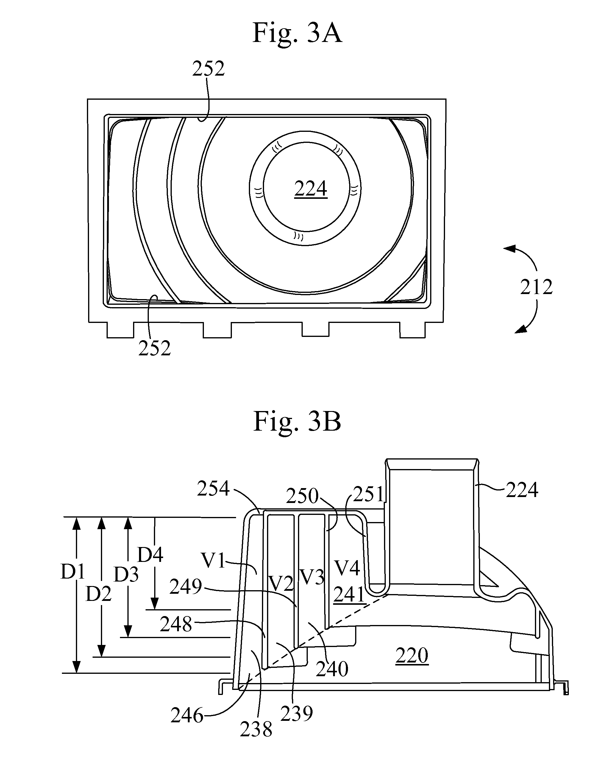
[0012]Another object of the present invention is to maintain and improve the structural integrity of air induction system housing components by replacing the low profile internal structural support ribbing of a housing, such as an air filter housing, with new set of relatively deep, contoured and spaced ribbing configured and adapted to define a low-loss airflow glide path, thereby providing a smoothly contoured flow path configured to reduce or eliminate recirculation patterns and reduce pressure drop in the air induction system. Airflow is guided by positioning of air pillow pockets over which the airflows rather than by provision of structural members such as walls or guide vanes.
[0013]Another object of the present invention is to size and configure the air pillow pockets to additionally serve as tuned resonance chambers within the housing to provide tuned acoustic countermeasures, eliminating the need to provide additional resonance chambers of the prior art.
[0014]A side benefit of the relatively deep, contoured and spaced air pillow pocket ribbing is in the improved structural support of portions of the air induction system housing, thereby stiffening the walls of the housing and reducing the radiation of engine noise from the air intake tract through the housing.
[0018]In another aspect of the invention, the air intake tract includes a housing having at least one wall with the housing defining an airflow cavity therein. The housing includes an airflow outlet port in airflow communication with the cavity with the airflow stream exiting through the outlet port. The ribs are each configured with an inwardly extending length into the cavity selected to correlate with a boundary of a low-loss airflow glide path of the airflow stream flowing from the cavity to the outlet port. The flow-static air masses in the air pillow pockets operate to guide the airflow stream along the low-loss airflow glide path to the outlet port and the air pillow pockets are configured and adapted to reduce airflow stream turbulence and / or airflow pressure loss by guiding the airflow stream along the low-loss flow path.

Problems solved by technology

These pulsations may result in undesired noises radiating from the intake tract.
Some of these noises or noise frequencies may be undesirable.
Undesired sounds may also be generated by the intake air flowing through a restriction or other geometry that introduces turbulence into the flow.
The generation of turbulence consumes energy from the airflow stream and may result in an increased restriction to airflow in the air intake tract.
Often the air filtration element has a larger surface area than the cross sectional area of either the inlet or outlet ports on the filter housing providing a more tortuous than desired airflow pattern in the housing and resulting in the generation of airflow turbulence within the air filter housing.
While these devices are useful in reducing transmitted noise in engine air intake tracts, none of the solutions address the problem of improving the airflow path in an air intake tract to minimize pressure loss and integration of acoustic countermeasure control technology into the airflow guidance solution.

Method used


Image

  • Air pillow flow guidance and acoustic countermeasure system for an air intake tract
  • Air pillow flow guidance and acoustic countermeasure system for an air intake tract
  • Air pillow flow guidance and acoustic countermeasure system for an air intake tract

Examples


Embodiment Construction

[0030]Before describing in detail embodiments that are in accordance with the present invention, it should be observed that the embodiments reside primarily in combinations of method steps and apparatus components related to an airflow guidance and acoustic countermeasures system for an air intake tract, for example, for an internal combustion engine. Accordingly, the apparatus components have been represented where appropriate by conventional symbols in the drawings, showing only those specific details that are pertinent to understanding the embodiments of the present invention so as not to obscure the disclosure with details that will be readily apparent to those of ordinary skill in the art having the benefit of the description herein.

[0031]In this document, relational terms such as first and second, top and bottom, and the like may be used solely to distinguish one entity or action from another entity or action without necessarily requiring or implying any actual such relationsh...


PUM

PropertyMeasurementUnit
Lengthaaaaaaaaaa
Pressureaaaaaaaaaa
Flow rateaaaaaaaaaa

Abstract

An air pillow system for an air intake tract includes a plurality of inwardly extending ribs arranged in a distally spaced arrangement and defining a plurality of peripherally closed air pillow pockets. Each pocket has an open end opening towards an airflow stream to be guided. Each rib is configured with an inwardly extending length selected to correlate with a boundary of a low-loss airflow glide path. The air pillows operate to guide the airflow stream along the low-loss airflow glide path with reduced airflow stream turbulence and airflow pressure loss.

Description

TECHNICAL FIELD[0001]This invention is related to an air pillow airflow guidance system for an air intake tract that may additionally be configured to provide tuned acoustic countermeasures to reduce targeted frequencies of noise in an air intake tract.BACKGROUND OF THE INVENTION[0002]Air intake systems for motor vehicles may include an air intake tract in which an air filter housing or other housing (for example, an acoustic resonance chamber, air plenum, etc) is arranged. Air filters are used to provide a necessary source of particulate free filtered air for safe operation of an internal combustion engine. Various types of noise silencers or resonance chambers may also be applied in the air intake tract of an engine to achieve attenuation of undesired engine operating noises transmitted in the intake tract.[0003]During the cylinder air intake cycle of the engine, a vacuum pulse is generated in the air intake tract by the opening and closing of the cylinder air intake valves. These...

Claims


Application Information

Patent Timeline
IPC IPC(8): F02M35/10
CPCB01D45/06B01D45/08B01D46/003B01D46/0031B01D46/0045F02M35/1216B01D2279/60F02M35/022F01N1/083F02M35/1211B01D50/002F02M35/14B01D50/20
Inventor MILLER, STUARTDESJARDINS, MICHAEL
Owner MANN HUMMEL GMBH
Learn More