Valve for a contact tray

A technology of contacting disc and valve body, applied in the field of valve contacting disc, can solve the problems of non-existence, wide working range, etc., and achieve the effect of fast installation speed

Inactive Publication Date: 2008-03-12
SULZER CHEMTECH AG
View PDF5 Cites 11 Cited by
  • Summary
  • Abstract
  • Description
  • Claims
  • Application Information

AI Technical Summary

Problems solved by technology

Sieve discs are common because they are simple and cheap, but they do not have the wide working range of valve discs

Method used


Image

  • Valve for a contact tray
  • Valve for a contact tray
  • Valve for a contact tray

Examples


Embodiment Construction

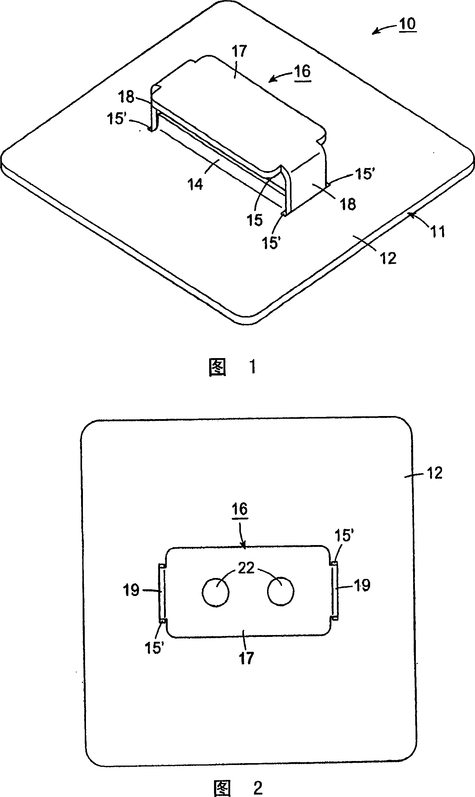
[0038] Referring to Figure 1, the injection valve 10 is particularly suitable for use with a contact pan 11, for example, in a distillation column using a downcomer. The valve 10 may be of the fixed type or of the movable (floating) type. Figure 1 shows a valve 10 of the movable type.

[0039] As shown, the contact plate 11 has a deck 12 for receiving a liquid flow thereon and a number of valves 10 (only one of which is shown) positioned in a row-by-row arrangement in a staggered array. In the plate surface 12, for example, in a triangular angle, or in a rectangular array, for example with right angles. Each valve 10 has a pair of parallel opposing walls 14 extending upwardly from the deck 12 to define an aperture 15 in the rectangular deck 12 for ascending steam flow, and a single-piece valve body 16. is arranged in the aperture 15 so as to move under the influence of the ascending steam flow from a closed position on the wall 14 to a raised position above the wall 14 (as s...


PUM


Abstract

The valve for a contract tray employs an aperture in a deck that is of rectangular or trapezoidal shape with upstanding walls at the sides of the aperture. The valve body is disposed in the aperture with a cover above the aperture and legs that extend downwardly to interfit with at least the upstream end of the walls to block the liquid flow. The valve body may be fixed or movable. In the movableembodiment, the valve body is seated on the walls about the aperture to close the aperture. The ascending vapor lifts the valve to allow bubbling of the vapor in the liquid on the deck.

Description

technical field [0001] The present invention relates to valves for contact discs. More specifically, the present invention relates to valves for gas-liquid contact trays suitable for use in distillation columns. Background technique [0002] As is known, distillation columns are provided with various types of contact trays for gas-liquid contacting purposes. Examples of such columns are described in US Patent Nos. 4,750,975; 5,120,474 and 5,453,222. [0003] Typically, contact trays in distillation columns and the like have decks over which liquid flows. In some cases, the deck is provided with valves through which ascending vapor can flow and over which liquid can flow in order to bubble the vapor through the liquid. In other cases, sieve trays are used which have only holes in the deck without any valves. Sieve discs are common because they are simple and cheap, but they do not have as wide a working range as valve discs. [0004] The valves used are of various config...

Claims


Application Information

Patent Timeline
Patent Type & Authority Applications(China)
IPC IPC(8): B01D3/20
CPCB01D3/163
Inventor M·W·皮林D·E·努特
Owner SULZER CHEMTECH AG
Why Eureka
Try Eureka