Orbiting combustion nozzle engine

a combustion nozzle and engine technology, applied in the field of engines, can solve the problems of inefficiency utilization, one weakness of prior art turbine engines, and b>10/b> in the turbine, and achieve the effects of reducing pressure drop, low vortex angular velocity, and reducing pressure drop

Inactive Publication Date: 2008-07-29
R JET ENG
View PDF16 Cites 11 Cited by
  • Summary
  • Abstract
  • Description
  • Claims
  • Application Information

AI Technical Summary

Benefits of technology

[0018]In U.S. Pat. No. 6,272,844 and the related U.S. Pat. No. 6,460,343 are taught engines having no inlet turbine stators. This is done in order to reduce the pressure drop at the turbine entrance. A vortex is created in the combustion chamber by the use of a swirler stator at the compressor outlet. This solution is inefficient as air at the compressor outlet has already been diffused at the rotor exit. By again expanding the air in the swirler, the pressure is further reduced.
[0019]The present invention avoids analogous pressure losses by substantially maintaining an airflow vortex produced by a compressor through a rotating combustion chamber and through a nozzle wheel.
[0020]Another disadvantage of the teachings of U.S. Pat. Nos. 6,272,844 and 6,460,343 is that therein the vortex is generated by a swirler for only for a portion of the compressor airflow. This results in a relatively low vortex angular velocity at the turbine inlet, reducing efficiency.

Problems solved by technology

One weakness of prior art turbine engines, such as 10 is in the turbine.
Thus even though high velocity gas jets can be easily obtained, these cannot be efficiently utilized due to the shortened lifetime of the turbine blades.
This results in low efficiency and a limited power output.
These turbineless engines have failed to gain popularity, amongst other reasons, due to an excessive moment of inertia and extreme hoop stress resulting from the positioning of the combustion chambers.
The primary disadvantage of this design is similar to the disadvantage of the turbineless engines described above: the combustion chambers (termed combustor baskets) undergo severe hoop stress.
An additional disadvantage of this design is that air is fed into the combustion chambers using a ram effect and consequently suffers severe aerodynamic entry losses.
Another weakness of prior art turbine engines, such as 10 is in the thermodynamics of the engine.
Thus, prior art turbine engines, such as 10, are inherently inefficient.
None of the alternative turbine engines described above presents a solution to the inherent thermodynamic inefficiency of the turbine engine.
This solution is inefficient as the air from the compressor is first diffused at the rotor exit and is again expanded in the swirler, reducing the pressure even further.

Method used


Image

  • Orbiting combustion nozzle engine
  • Orbiting combustion nozzle engine
  • Orbiting combustion nozzle engine

Examples


Embodiment Construction

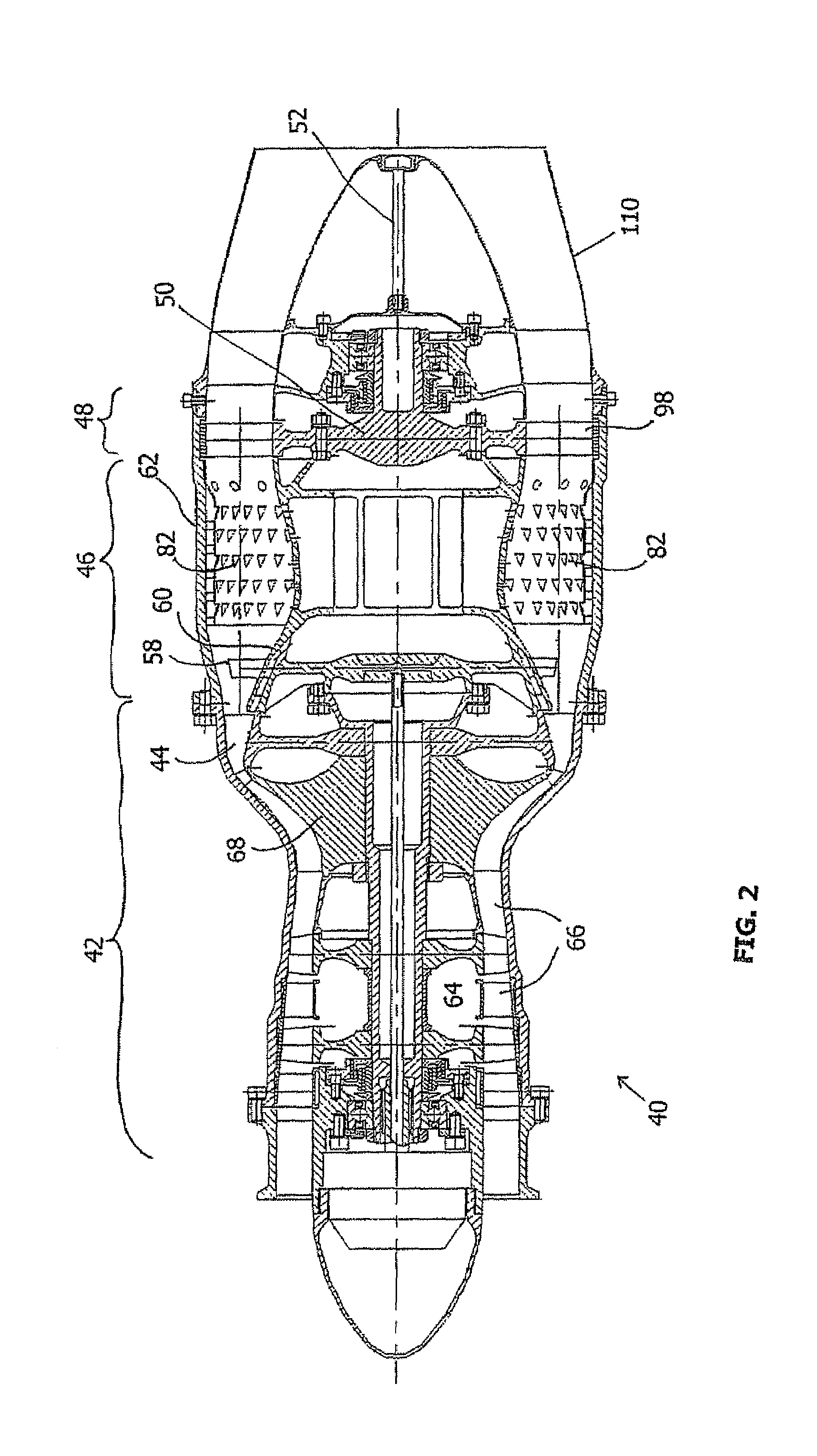
[0051]The engine of the present invention is characterized in having a rotating assembly comprising a co-rotating compressor and nozzle wheel enclosed within a non-rotating outer casing, thus defining a rotating combustion chamber. Since, in contrast to prior art turbines, in the engine of the present invention there is no turbine wheel and torque is generated using a rotating nozzle wheel, and because combustion occurs in a vortex of air rotating together with the rotating assembly, the engine of the present invention is called an orbiting combustion nozzle (OCN) engine.

[0052]The principles and operation of an OCN engine according to the present invention may be better understood with reference to the drawings and the accompanying description. In the drawings, like references designate equivalent parts

[0053]A typical, non-limiting, embodiment of an OCN engine 40 is schematically depicted in FIG. 2. This depiction, and other depictions below, are primarily in cross section. It will ...


PUM


Abstract

An orbiting combustor nozzle (OCN) engine, having a rotating assembly comprising a co-rotating compressor and nozzle wheel enclosed within a non-rotating outer casing, defining a rotating combustion chamber, is disclosed. Combustion occurs in the combustion chamber in a vortex of gas that rotates at the same angular velocity as the rotating assembly. Also disclosed, is a method of cooling a blade of a rotating wheel, such as a turbine wheel or nozzle wheel, by projecting cool air at the base of the vane form a nozzle corotating with the blade. Such cooling is easily implemented in an OCN engine with use of an innovative annular combustor. Also disclosed is a method of countering axial backflow by use of a combustion chamber compressor.

Description

FIELD AND BACKGROUND OF THE INVENTION[0001]The present invention relates to an engine and specifically to an engine having a rotating assembly comprising a co-rotating compressor and compressor-driving nozzle wheel enclosed within a non-rotating outer casing, thus defining a rotating combustion chamber.[0002]In a conventional turbine engine 10, depicted in FIG. 1, one or more non-rotating combustion chambers 12 are found between a compressor 14 and a turbine 16. Compressor rotor 18 and turbine wheel 20 are attached to a common rotating shaft 22. During operation of engine 10, compressor 14 forces air into engine 10 towards combustion chambers 12. Non-rotating terminal stator vanes 24 in compressor 14 direct air at high pressure into combustion chambers 12 through what is generally called a diffuser or diffusion stage. In combustion chambers 12 fuel is mixed with the high pressure air. The fuel-air mixture burns and as a result of the released heat, the exhaust expands outwards throu...

Claims


Application Information

Patent Timeline
Patent Type & Authority Patents(United States)
IPC IPC(8): F02C3/14F02C3/34F02C7/18F02BF23R3/52F02C3/16F02C7/12F23R3/06F23R3/18F23R3/28F23R3/56
CPCF02C3/16F02C7/12F23R3/50F23R3/56F23R3/38Y02T50/675Y02T50/60
Inventor LIOR, DAVID
Owner R JET ENG
Why Eureka
Try Eureka