Backlight unit and liquid crystal display
A technology of backlight unit and light-emitting element, applied in optical elements, lighting devices, optics, etc., can solve the problems of uneven brightness and reduced image quality, and achieve the effect of suppressing uneven brightness
- Summary
- Abstract
- Description
- Claims
- Application Information
AI Technical Summary
Problems solved by technology
Method used
Image

Examples
Embodiment approach 1
[0068] An embodiment will be described below with reference to the drawings. In addition, depending on the drawings, part numbers and the like may be omitted for convenience, and in such cases, other drawings may be referred to. In addition, black dots on the drawings indicate directions perpendicular to the paper surface.
[0069] Figure 29 It is an exploded perspective view of the liquid crystal display device 79 . As shown in the figure, a liquid crystal display device 79 includes a liquid crystal display panel 71 and a backlight unit 72 .
[0070] The liquid crystal display panel 71 is a non-luminous display panel, and performs a display function by receiving light (backlight) from a backlight unit 72 . Therefore, if the light from the backlight unit 72 can uniformly illuminate the entire surface of the liquid crystal display panel 71, the display quality of the liquid crystal display panel 71 will be improved.
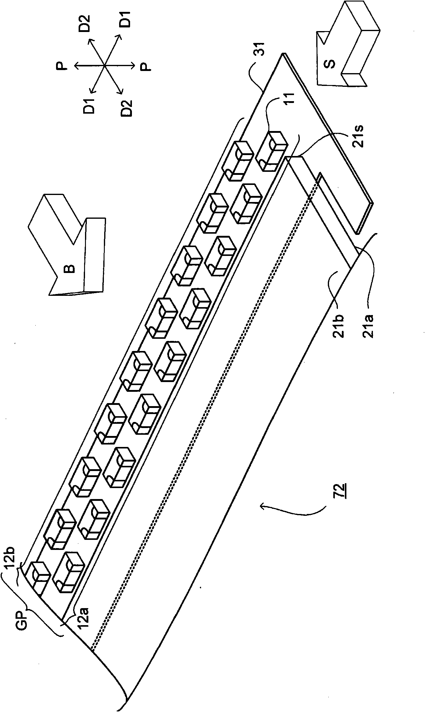
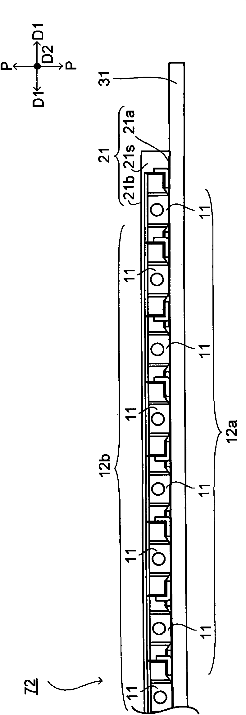
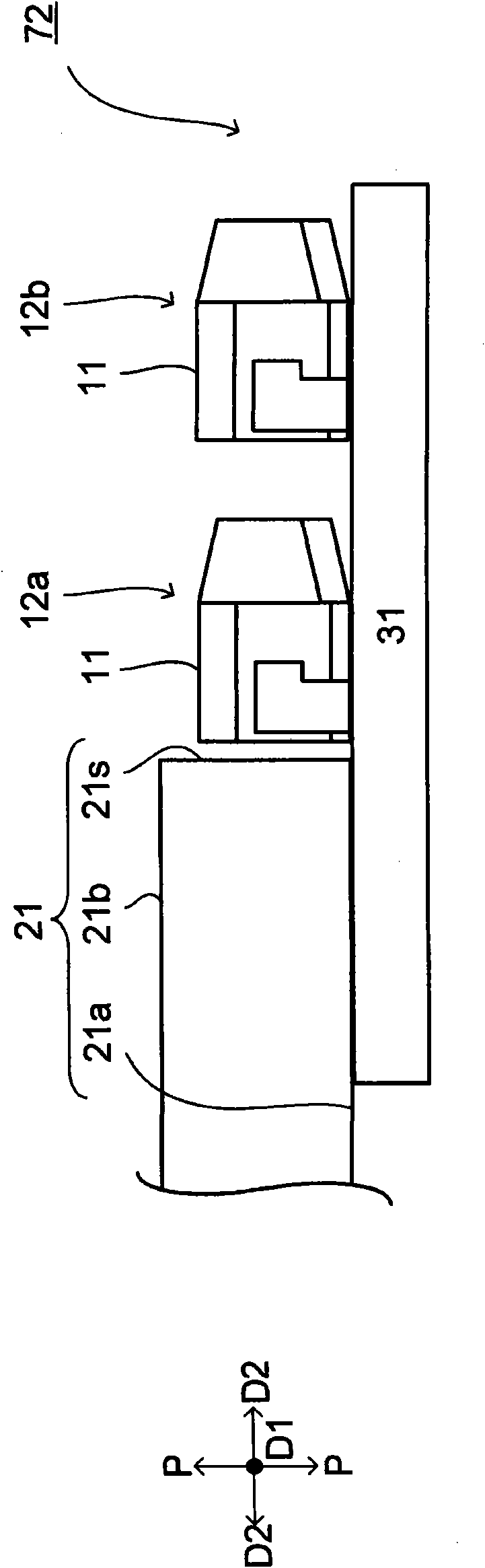
[0071] The backlight unit 72 includes an LED (Light Emi...
Embodiment approach 2
[0090] Embodiment 2 will be described. In addition, components having the same functions as those used in Embodiment 1 are denoted by the same symbols, and description thereof will be omitted.
[0091] In Embodiment 1, it was exemplified that one LED 11 in the LED row 12b of the two LED rows 12a, 12b illuminates the backlight unit 72 between the LEDs 11, 11 in the LED row 12a. However, it is not limited to this.
[0092] For example, if Figure 6 ~ Figure 10 (also, Figure 6 ~ Figure 10 description with Figure 1 to Figure 5 same), the two LEDs 11, 11 in the LED row 12b may illuminate the backlight unit 72 between the LEDs 11, 11 in the LED row 12a.
[0093] Specifically, the interval La2 of the arrangement pitch of the LEDs 11 in the LED row 12a is different from the interval Lb2 of the arrangement pitch of the LEDs 11 in the LED row 12b (La2>Lb2), and the first optical path BLa of the LEDs 11 in the LED row 12a The second light path BLb of the LEDs 11 in the LED row 12b...
Embodiment approach 3
[0097] Embodiment 3 will be described. In addition, components having the same functions as those used in Embodiment 1 are denoted by the same symbols, and description thereof will be omitted.
[0098] In the backlight unit 72 according to Embodiments 1 and 2, the LED group GP is mounted on the FPC board 31 facing only the bottom surface 21 a (non-light-emitting surface 21 a ) of the light guide plate 21 . However, it is not limited to this. For example, if Figure 11 ~ Figure 16 As shown, the LEDs 11 of the LED group GP may be dispersedly mounted on the FPC boards 31 a and 31 b facing the bottom surface 21 a and the top surface 21 b (light exit surface 21 b ) of the light guide plate 21 .
[0099] Next, the LEDs of the LED group GP are respectively mounted on the FPC board (non-light-emitting surface side FPC board) 31a facing the bottom surface 21a of the light guide plate 21 and the FPC board (light-emitting surface side FPC board) 31b facing the top surface 21b. Backlig...
PUM
 Abstract
Description
Claims
Application Information
 - R&D
- Intellectual Property
- Life Sciences
- Materials
- Tech Scout
- Unparalleled Data Quality
- Higher Quality Content
- 60% Fewer Hallucinations
Browse by: Latest US Patents, China's latest patents, Technical Efficacy Thesaurus, Application Domain, Technology Topic, Popular Technical Reports.
© 2025 PatSnap. All rights reserved.Legal|Privacy policy|Modern Slavery Act Transparency Statement|Sitemap|About US| Contact US: help@patsnap.com