Eureka AIR delivers breakthrough ideas for toughest innovation challenges, trusted by R&D personnel around the world.

Circuit arrangement and actuation method for semi-conductor light sources

A circuit device and semiconductor technology, applied in the field of projection equipment, can solve the problems that the processing speed cannot be reached, the minimum on-time duration depends on the processing speed of the driving electronic device, and the logic circuit is expensive.

Inactive Publication Date: 2010-03-24
OSRAM GMBH
View PDF0 Cites 0 Cited by
  • Summary
  • Abstract
  • Description
  • Claims
  • Application Information

AI Technical Summary

Problems solved by technology

However, this is problematic when switching off, since the minimum on-duration depends on the processing speed of the drive electronics
For this reason, the drive electronics must have fast logic circuits and fast analog / digital converters, since otherwise the drive electronics cannot achieve the required processing speed
However, fast analog-to-digital converters and fast logic circuits (such as high-speed clocked microcontrollers) are very expensive, which has an adverse effect on the pricing of the final product)

Method used


Image

  • Circuit arrangement and actuation method for semi-conductor light sources
  • Circuit arrangement and actuation method for semi-conductor light sources
  • Circuit arrangement and actuation method for semi-conductor light sources

Examples


Embodiment Construction

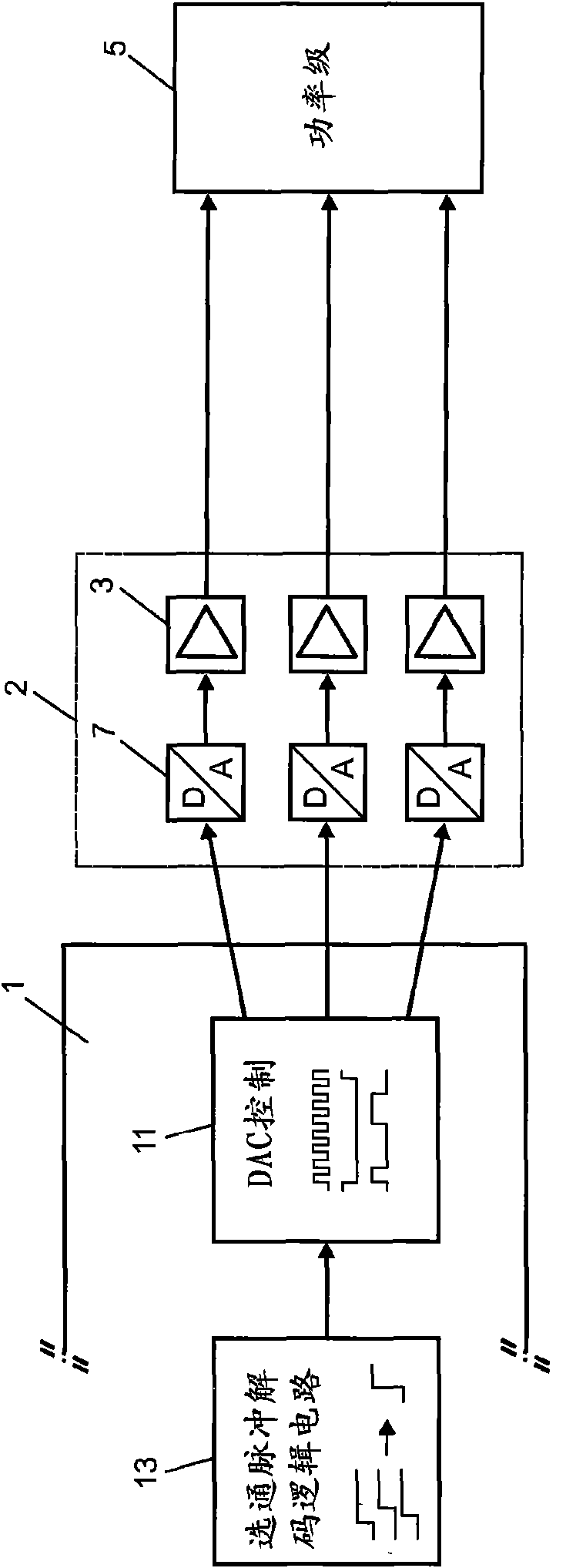
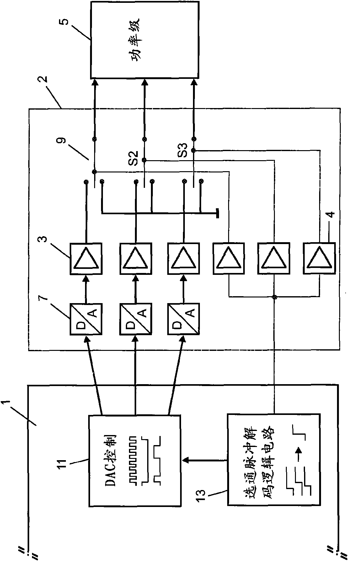
[0012] FIG. 1 shows a block circuit diagram of a circuit arrangement according to the prior art. The digital part of the drive electronics 1 comprises timing signal decoding logic 13 and control logic 11 for the digital / analog converter 7 . The analog part includes a digital / analog converter 7 , a control logic circuit 3 and a light emitting diode module 5 . The light emitting diode module 5 includes a power driver for the LEDs and the LEDs themselves. An analog brightness signal is input to the power driver, so that the LED is then switched on to the desired brightness level or switched off in the case of an analog signal corresponding to logic 0. The timing signal decode logic receives a timing signal "strobe" from the video electronics (not shown). The timing signal is processed and the timing signal decoding logic outputs an activation signal to the control logic 11 at the correct moment. The logic circuit reads a table generated by the video electronics in which timing...


PUM


Abstract

The invention relates to a circuit arrangement and a actuation method for actuating semi-conductor light sources, comprising video electronics producing a timing signal (int Strobe) and an image valuetable, a driver circuit made of a digital (1) and an analog (3, 7) part, and a semi-conductor light source module (5), which may comprise one or more semi-conductor light sources, wherein between thedriver circuit and the semi-conductor light source module a switch (S1, S2,...) is disposed, which is actuated by the driver circuit and which can switch the signal controlling the target brightnessof the semi-conductor light source module to ground after the digital-to-analog converter (7) processing. The use of the switch enables the production of very short light pulses, the minimum pulse duration of which is independent of the delay time of the digital-to-analog converter.

Description

technical field [0001] The invention relates to projection devices equipped with semiconductor light sources. In particular microdisplay applications for front and rear projection are mentioned here. Background technique [0002] High-power semiconductor light sources such as high-power light-emitting diodes have recently been increasingly used in applications currently reserved for high-pressure discharge lamps. Precisely in the field of projection, semiconductor light sources are not driven continuously but pulsed in order to meet the requirements there. In this case, very short pulses are used, which have a very high power density for this purpose. [0003] In display applications, multiple colors are used, usually at least 3 colors. The driver circuit is divided into video electronics, which process the input signal, and drive electronics, which are usually divided into a digital part and an analog part, which are connected via a digital / analog converter. The video e...

Claims


Application Information

Patent Timeline
Patent Type & Authority Applications(China)
IPC IPC(8): G09G3/34H05B33/08H05B44/00
CPCH05B33/0818G09G2310/0235Y02B20/346G09G2320/0653G09G2320/064H05B33/086G09G2310/0237G09G2320/0633G09G3/3413H05B45/20H05B45/327Y02B20/30
Inventor 拉尔夫·希英彼得·尼德迈尔
Owner OSRAM GMBH
Why Eureka
Eureka Blog
Learn More