Cutting and bending device and membrane cutting and bending method

A bending device and cutting technology, which is applied in the field of cutting and bending devices, can solve the problems of reduced strength of the diaphragm, waste of time and manpower, and easy damage, and achieve the effect of good strength and not easy to return to shape

Inactive Publication Date: 2010-03-31
BENQ MATERIALS +1
View PDF0 Cites 2 Cited by
  • Summary
  • Abstract
  • Description
  • Claims
  • Application Information

AI Technical Summary

Problems solved by technology

[0003] The above-mentioned method of bending the diaphragm requires a separate process, which wastes time and manpower; at the same time, the strength of the diaphragm at the incision line 91 decreases, which is prone to damage

Method used


Image

  • Cutting and bending device and membrane cutting and bending method
  • Cutting and bending device and membrane cutting and bending method
  • Cutting and bending device and membrane cutting and bending method

Examples


Embodiment Construction

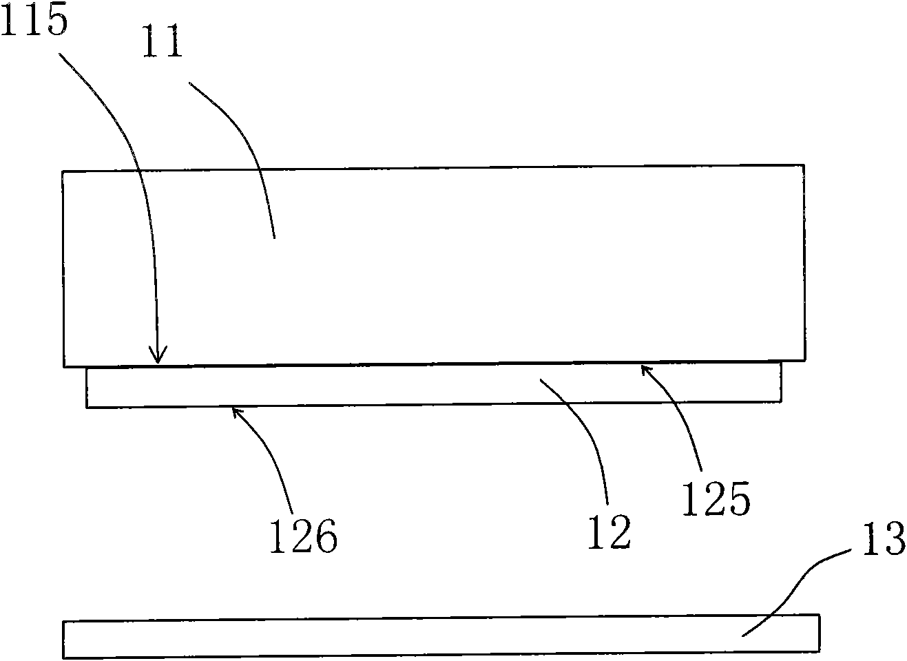
[0019] Please refer to Figure 3 to Figure 6 , image 3 It shows a schematic front view of a cutting and bending device according to an embodiment of the present invention; Figure 4 painted image 3 Schematic diagram of a partially enlarged front view of the cutting die in the cutting and bending device shown; Figure 5 painted image 3 The schematic bottom view of the cutting die in the cutting and bending device shown; Figure 6 painted image 3 A schematic top view of the support table in the cutting and bending device shown. The cutting and bending device of this embodiment includes: a positioning table 11, the positioning table 11 has a positioning surface 115; a cutting die 12 having opposite first surfaces 125 and second surfaces 126, the first The surface 125 is positioned on the positioning surface 115 (it can be positioned by means of screw locking, side strip clamping, etc.); the second surface 126 of the knife mold 12 is vertically provided with a cutting kn...


PUM


Abstract

The invention relates to a cutting and bending device and a membrane cutting and bending method. The cutting and bending device comprises a positioning table, a cutting die, a cutter, a fold fin, a heater and a supporting table, wherein the positioning table has a positioning surface; the cutting die has a first surface and a second surface which are opposite, and the first surface is positioned on the positing surface; the cutter and the fold fin are vertically arranged on the second surface of the cutting die; the heater is arranged in the cutting die and heats the fold fin; and the supporting table is arranged in a way of corresponding to the second surface of the cutting die.

Description

【Technical field】 [0001] The invention relates to a cutting and bending device, in particular to a membrane cutting and bending device and a membrane cutting and bending method. 【Background technique】 [0002] In the production process of many membranes, a cutting step is required, which cuts a large sheet or strip of membranes into membranes of appropriate size. Some diaphragms need to be bent after cutting, such as figure 1 and figure 2 A diaphragm bending method in the prior art is shown, which firstly shows figure 1 As shown, discrete cutting is carried out at the predetermined bending place of the diaphragm 90 to form intermittent incision lines 91; figure 2 The membrane 90 is shown bent along intermittent cut lines 91 . [0003] The above-mentioned method of bending the membrane requires a separate process, which wastes time and manpower; meanwhile, the strength of the membrane at the incision line 91 decreases, which is prone to damage. 【Content of invention】 ...

Claims


Application Information

Patent Timeline
Patent Type & Authority Applications(China)
IPC IPC(8): B29C53/06B29C53/80B29C53/84
Inventor 顾国民
Owner BENQ MATERIALS
Why Eureka
Try Eureka