
Method for velocity analysis using waveform inversion in laplace domain for geophysical imaging

A technology of Laplace domain and Laplace transform, applied in the field of velocity analysis, can solve problems such as difficulty in obtaining long-wavelength velocity models, unclear successful implementation of waveform inversion of pre-stack reflection data, lack of low-frequency components, etc.

Inactive Publication Date: 2010-03-31
SHINS GEOPHYSICS
View PDF0 Cites 9 Cited by
  • Summary
  • Abstract
  • Description
  • Claims
  • Application Information

AI Technical Summary

Problems solved by technology

However, the successful implementation of waveform inversion of collected prestack reflection data for real has been unclear
One obstacle for successful implementation is the lack of low-frequency components in the real numbers, which makes it difficult to derive long-wavelength velocity models
Another reason preventing successful waveform inversion for real numbers is the possibility of non-unique solutions for subsurface images or velocity models

Method used


Image

  • Method for velocity analysis using waveform inversion in laplace domain for geophysical imaging
  • Method for velocity analysis using waveform inversion in laplace domain for geophysical imaging
  • Method for velocity analysis using waveform inversion in laplace domain for geophysical imaging

Examples


Embodiment Construction

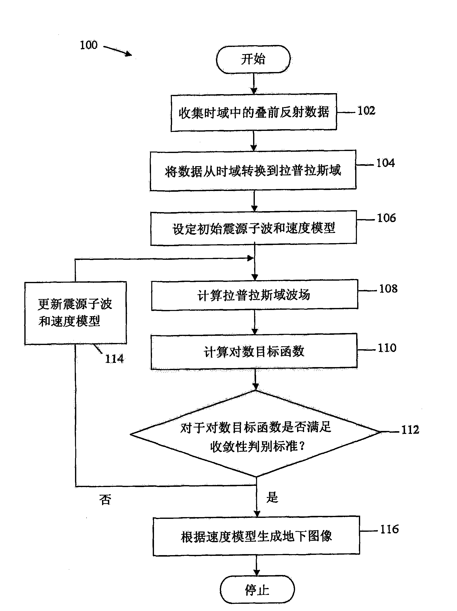
[0017] It should be understood at the outset that although an exemplary implementation of one or more embodiments is provided below, the disclosed systems and / or methods may be implemented using any number of techniques, whether currently known or in existence . The present disclosure should not be limited in any way to the exemplary implementations, drawings, and techniques shown below, including the exemplary designs and implementations shown and described herein, but rather should be limited within the scope of the appended claims and their The full range of equivalents is modified.

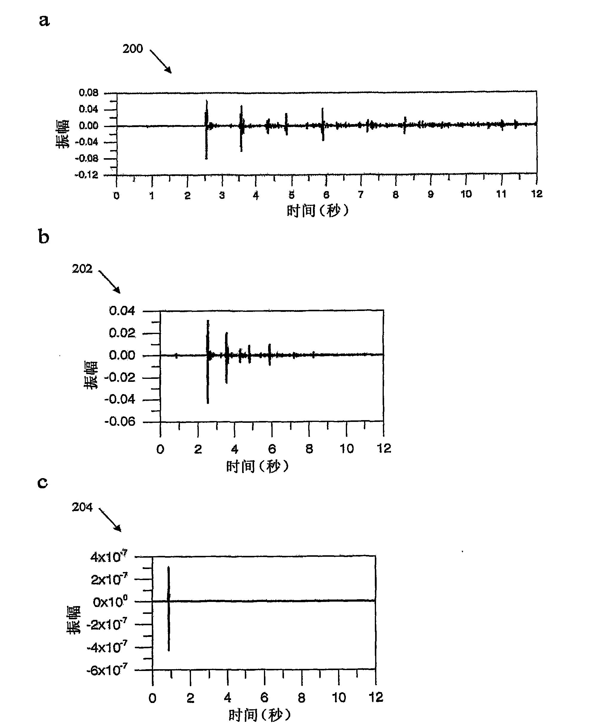
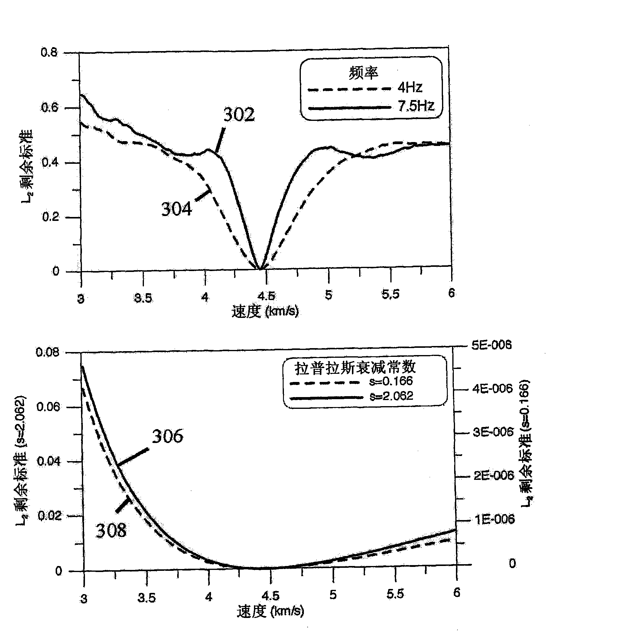
[0018] Disclosed herein is a waveform inversion method in the Laplace domain for building a subsurface velocity model from prestack reflection data. A wavefield in the Laplace domain may be equivalent to a zero frequency component or a frequency component close to zero of an evanescent wavefield in the time domain. Thus, wavefield inversion in the Laplace domain may share similar properties ...


PUM


Abstract

A Laplace transform system comprising a processor, a measured time domain wavefield, a velocity model, and Laplace damping constants, wherein the processor is programmed to calculate a substantially about zero frequency component of a Fourier transform of a time domain damped wavefield, wherein the time domain damped wavefield is damped by the Laplace damping constants to obtain long wavelength velocity information for deeper subsurface regions.

Description

technical field [0001] The present invention relates to a method for velocity analysis using waveform inversion in the Laplace domain for geophysical imaging. Background technique [0002] Seismic imaging is used for various purposes, for example, to search for underground oil and gas deposits. In seismic imaging, a physical image of the subsurface or an associated subsurface information model (eg, a velocity model) is constructed from collected seismic measurements. One type of collected seismic data is prestack reflection data in the time domain. Typically, to collect prestack reflection data, multiple dedicated sources are used to send acoustic or elastic waves into the ground. Seismic sources are usually scattered over the upper surface to cover certain areas of interest. Reflected seismic waves from the subsurface are then collected at the upper surface using multiple specialized receivers covering the area of ​​interest. Subsurface images or associated velocity mod...

Claims


Application Information

Patent Timeline
Patent Type & Authority Applications(China)
IPC IPC(8): G01V3/08G06F17/14
CPCG01V1/303G01V1/28G01V2210/67G01V1/24
Inventor 申昌秀
Owner SHINS GEOPHYSICS
Learn More