
Two-station mandrel mechanism for serially connected knitting of metal ring chain

A metal ring and two-station technology, applied in the direction of metal chains, etc., can solve the problems of difficult maintenance and replacement of parts, large device volume, complex structure, etc., and achieve the effects of reducing labor intensity of workers, high production efficiency, and improving production efficiency

Active Publication Date: 2011-08-03
王洪军
View PDF0 Cites 0 Cited by
  • Summary
  • Abstract
  • Description
  • Claims
  • Application Information

AI Technical Summary

Problems solved by technology

Domestically, there is still no automatic production of medium and large-sized metal forged circular link chains in series, but the current international advanced medium and large-sized metal circular chain automatic serial connection and weaving equipment uses two sets of mandrel molds on two sides. It is completed at one station, and the imported equipment is large in size, complex in structure, expensive, and it is more difficult to maintain and replace other parts, which is unbearable for general manufacturers.

Method used


Image

  • Two-station mandrel mechanism for serially connected knitting of metal ring chain
  • Two-station mandrel mechanism for serially connected knitting of metal ring chain
  • Two-station mandrel mechanism for serially connected knitting of metal ring chain

Examples


Embodiment Construction

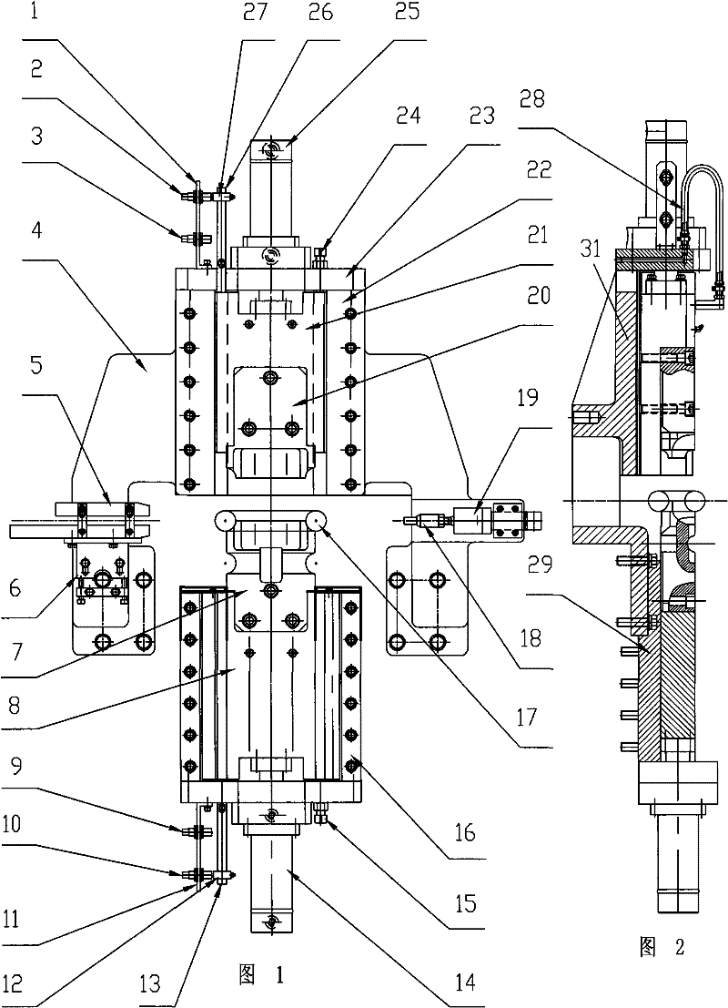
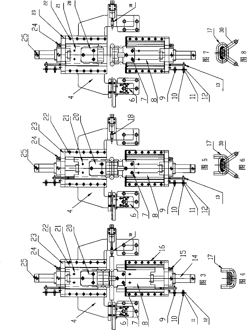
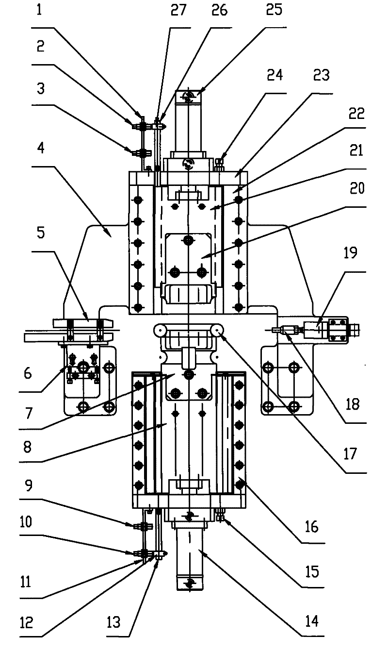
[0021] Such as figure 1 Shown: The two-station mandrel mechanism for braiding metal ring chains in series is composed of three parts. It includes: an upper mandrel device; a special lower mandrel device; a gantry bracket for fixing the upper mandrel device is fixed on the front upper part of the main body of the chain knitting equipment.

[0022] The gantry support for fixing the upper mandrel device includes a gantry support 4, a limit guide plate 5, a guide adjustment plate 6, a positioning block 18, a positioning oil cylinder 19, etc. The gantry support 4 is fixed on the front upper part of the main body of the equipment, and the upper sliding seat 21 is embedded in the chute on the upper sliding seat body 31 on the gantry support 4; the limit guide plate 5 and the guide adjustment plate 6 are fixed on the left feeding position of the gantry support 4, and the positioning block 18 and the positioning cylinder 19 are fixed on the gantry The right stopper position of bracket...


PUM


Abstract

The mechanism of the invention relates to a two-station mandrel device for completing the serially connected knitting of a metal ring chain at a same station, in particular to a two-station mandrel mechanism for serially connected knitting of the metal ring chain. The method comprises the following steps: an upper mandrel cylinder works to lead an upper mandrel to be at an upper position, a lowermandrel cylinder works simultaneously to lead a lower mandrel to be also at the upper position, so that a U-shaped ring is knitted; the upper mandrel cylinder works inversely to lead the upper mandrel to be at a lower position, the lower mandrel cylinder works inversely simultaneously to lead the lower mandrel to be also at the lower position, thus knitting a ring chain in a serially connection manner; the upper mandrel cylinder works inversely once again to lead the upper mandrel to be at the upper position, the lower mandrel is still at the lower position, then, other auxiliary mechanisms accomplish the action of taking out the knitted ring chain; and the processes are repeated automatically. The mechanism of the invention combines the two-station mandrel device with a knitting mainframe and other auxiliary mechanisms, and PLC conducts automatic procedure control, so that two stations for bar material forming and serially connected knitting are automatically accomplished on a same mandrel mechanism. The two-station mandrel mechanism is characterized by compact and reasonable structure, high production efficiency, high automation degree, stable production process and safety and reliability.

Description

technical field [0001] The technology of the invention relates to a mandrel device in the production process of full-automatic chain knitting of metal circular chains, in particular to a two-station mandrel mechanism for series knitting of metal circular chains. Background technique [0002] With the development of coal mining equipment, the height of medium and large-sized metal round link chains has been further reduced during the working process. The current solution is to use metal forged round link chains (compact rings) and knit them in series. to realise. Domestically, there is still no automatic production of medium and large-sized metal forged circular link chains in series, but the current international advanced medium and large-sized metal circular chain automatic serial connection and weaving equipment uses two sets of mandrel molds on two sides. It is completed at each station, and the device of this imported equipment is large in size, complex in structure, ex...

Claims


Application Information

Patent Timeline
Patent Type & Authority Patents(China)
IPC IPC(8): B21L1/02
Inventor 王洪军秦保翔郑卫
Owner 王洪军
Learn More