
Photoelectric sensing type cavity observing window

A technology of photoelectric induction and observation window, which is applied in the field of cavity observation window, can solve problems such as increased maintenance difficulty, difficult cleaning, inconvenient assembly and disassembly of observation window seat, etc., to ensure uniformity and compactness, reduce maintenance time, and install Effects that are extremely easy to debug

Inactive Publication Date: 2011-05-11
DONGGUAN ANWELL DIGITAL MASCH CO LTD
View PDF4 Cites 0 Cited by
  • Summary
  • Abstract
  • Description
  • Claims
  • Application Information

AI Technical Summary

Problems solved by technology

Since the observation window seat and the glass, and between the glass and the cavity are fixed together with a sealant to meet the vacuum requirements of the device during coating, it is inconvenient to assemble and disassemble the observation window seat, and it is difficult to clean, which increases maintenance costs. difficulty
At the same time, since the sensor is installed on the glass near the opening of the observation hole of the cavity, the sensor is easily adhered by the paint when the device is coated, making it impossible to accurately monitor the coating of the device in the cavity for vacuum coating. conditions, thus affecting the uniformity and compactness of the coating layer of the device, thereby shortening the normal service life of the device, and it is extremely inconvenient to debug and install the sensor installed at the opening of the viewing window near the cavity

Method used


Image

  • Photoelectric sensing type cavity observing window
  • Photoelectric sensing type cavity observing window
  • Photoelectric sensing type cavity observing window

Examples


Embodiment Construction

[0019] In order to describe in detail the technical content and structural features of the observation window of the photoelectric induction cavity of the present invention, further description will be made below in conjunction with the embodiments and accompanying drawings.

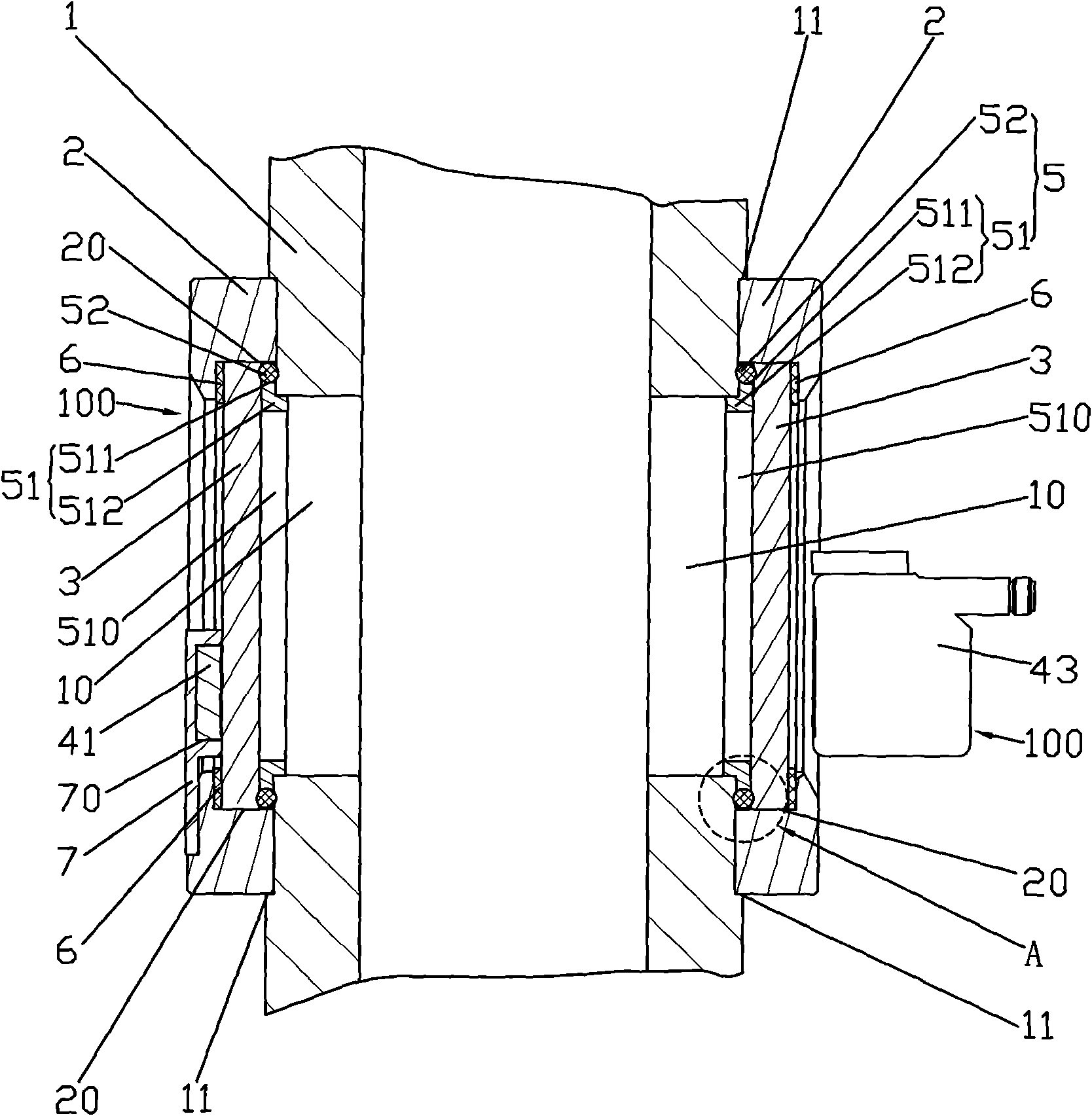
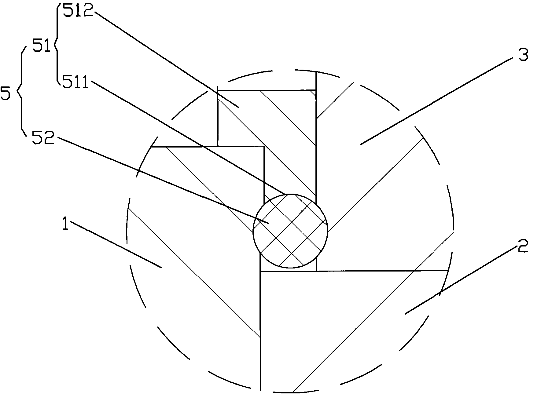
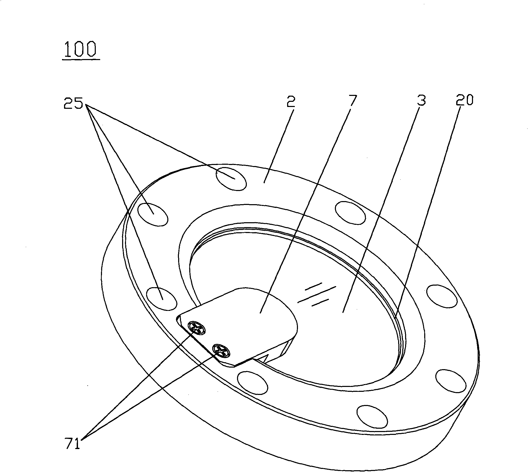
[0020] Such as figure 1 and image 3 As shown, the photoelectric induction cavity observation window 100 of the present invention is installed in the cavity 1 for coating. The photoelectric induction cavity observation window 100 includes a flange seat 2 , a sensor device and a glass plate 3 . The flange seat 2 is fixed on the cavity body 1 through mounting holes 25 and screws (not shown in the figure). The flange seat 2 has a hollow structure, and the hollow structure forms a receiving cavity 20 . The cavity 1 is provided with an observation channel 10 corresponding to the storage cavity 20 . The glass plate 3 is accommodated in the receiving chamber 20 and seals the observation channel 10 . Wherein...


PUM


Abstract

The invention provides a photoelectric sensing type cavity observing window which is mounted on a cavity and is used for film coating. The photoelectric sensing type cavity observing window comprises a flange seat, a sensor device, a glass plate and a sealing part, wherein the flange seat is mounted on the cavity and has a hollow structure which forms a containing cavity; the cavity is provided with an observing channel corresponding to the containing cavity; the glass plate is contained in the containing cavity and seals the observing channel; and the sealing part comprises a compression ring and a sealing ring. The compression ring is supported between the glass plate and the cavity, contained in the containing cavity and provided with an observing window corresponding to the observing channel; the outer side of the compression ring is provided with a compression ring groove matched with the sealing ring; one end of the sealing ring contacts with the compression ring groove, and the other end contacts with the inner wall of the containing cavity. A sensor device is mounted on the flange seat and extends to a position over the containing cavity. The photoelectric sensing type cavity observing window has excellent sealing performance, is very easy to maintain and can precisely monitor the film coating status of a device in the cavity.

Description

technical field [0001] The invention relates to a cavity observation window, in particular to a photoelectric induction cavity observation window capable of real-time observation and monitoring of the coating status of devices in the cavity used for coating. Background technique [0002] With the rapid development of the economy and the continuous improvement of the technical level, the pace of industrialization has been accelerated, and the industrialization is moving towards large-scale, complex, intelligent and precise directions, so as to better serve people's lives and economic development. Provide a steady stream of power. Among them, the OLED manufacturing industry is one of many precision industries. [0003] OLED stands for Organic Light-Emitting Diode (Organic Light-Emitting Diode), also known as Organic Electroluminescence Display (OELD). Because of its thinness, power saving and other characteristics, it has been widely used on the display screen of digital pro...

Claims


Application Information

Patent Timeline
Patent Type & Authority Patents(China)
IPC IPC(8): C23C14/52
Inventor 杨明生刘惠森范继良郭远伦王曼媛王勇
Owner DONGGUAN ANWELL DIGITAL MASCH CO LTD
Learn More