Safety pressure-limiting valve

A pressure-limiting valve and safety technology, which is applied in safety valves, balance valves, valve devices, etc., can solve the problems that the pressure relief hole diameter cannot be enlarged, the pressure relief speed is not fast enough, and the control sensitivity is reduced, so as to achieve reliable performance, The effect of small working resistance and good control sensitivity

Active Publication Date: 2010-04-21
夏育红
View PDF0 Cites 7 Cited by
  • Summary
  • Abstract
  • Description
  • Claims
  • Application Information

AI Technical Summary

Problems solved by technology

Because the diameter of the pressure relief hole of the passive pressure limiting valve cannot be made large, that is to say, its pressure relief speed is not fast enough.
[0006] For the active pressure limiting valve: the rubber membrane expands and pulls the lever to pressurize the cover plug, and the area of ​​the covered hole cannot be increased, otherwise the covering force of the cover plug will increase, so the force required to open the cover head is It needs to be increased, so the pressure of the pressure spring must be increased, and the increase of the spring pressure will cause the decrease of the control sensitivity. To increase the sensitivity, the hardness and tension of the rubber membrane must be increased, and the increase of the hardness will lead to the decrease of the control sensitivity. The stretching distance will be reduced, so under high pressure and long-distance stretching, it is easy to cause damage to the rubber film
Therefore, most of the safety pressure limiting valves with large displacement on the market have a short service life and it is difficult to improve the quality, which is for this reason.

Method used


Image

  • Safety pressure-limiting valve
  • Safety pressure-limiting valve
  • Safety pressure-limiting valve

Examples


Embodiment 1

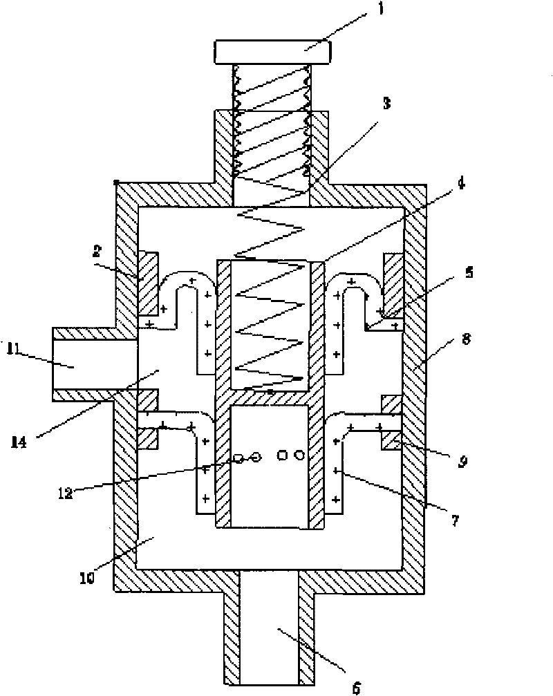
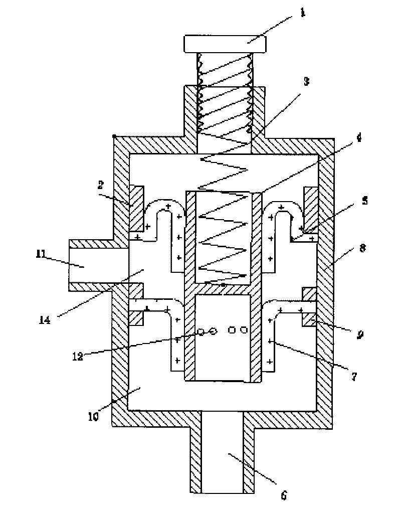
[0018] figure 1 It is a schematic cross-sectional structure of Embodiment 1; it includes a valve body 8 and a valve stem 4, and two upper and lower limit rings 2, 9 are built in. The valve stem 4 is placed in the valve body 8. The valve stem 4 is a cylindrical hollow body with a partition 13 inside, so that the hollow body is divided into an upper section and a lower section that are not connected to each other; The valve hole is 12, and there are two valve sleeves on the valve stem, that is, the sealing valve sleeve 5 and the opening and closing valve sleeve 7. The inner edges of the two valve sleeves are fixed on the periphery of the valve stem, and the outer edges of the valve sleeves are fixed on the valve body. around the cavity wall. The outer edge of the valve sleeve is sealed by limit rings 2 and 9, and an output chamber 14 is formed between the two valve sleeves to connect with the output port 11. The opening and closing valve sleeve 7 forms an input cavity 10 with ...

Embodiment 2

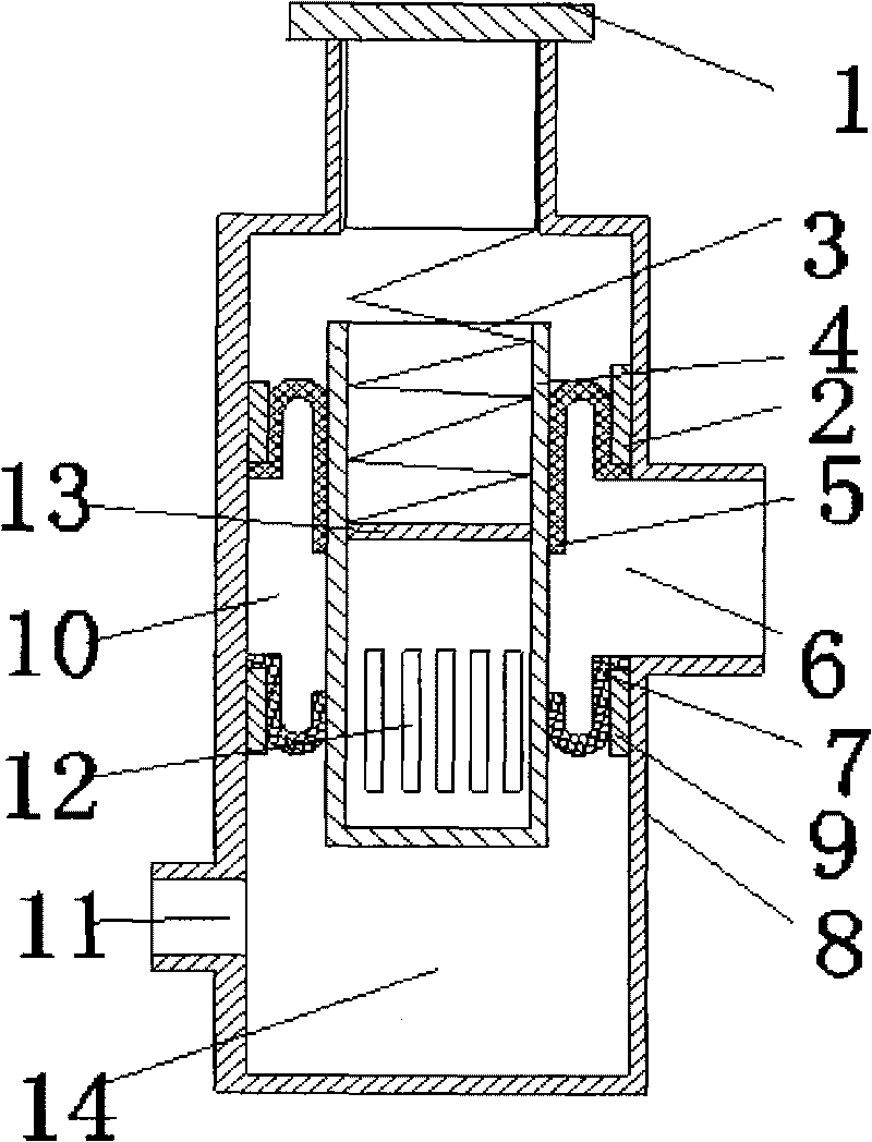
[0024] figure 2 It is a schematic diagram of the cross-sectional structure of the second embodiment. Including the valve body 8 and the valve stem 4, the upper and lower limit rings 2 and 9 are arranged inside the valve body 8. The valve stem 4 is placed in the valve body. The valve stem 4 is a cylindrical hollow body with a partition 13 inside, so that the hollow body is divided into an upper section and a lower section that are not connected to each other; 12. The valve hole is designed as a long row of holes. Two valve sleeves are arranged on the valve stem, that is, the sealing valve sleeve 5 and the opening and closing valve sleeve 7, and the inner edges of the two valve sleeves are all affixed to the periphery of the valve stem 4. The outer edge of the valve sleeve is all fixedly connected to the periphery of the inner cavity wall of the valve. The outer edge of the valve sleeve is sealed with upper and lower limit rings 2 and 9 respectively. An input cavity 10 and ...


PUM


Abstract

The invention discloses a safety pressure-limiting valve, which comprises a valve body and a valve stem, wherein the valve stem is arranged in the valve body; the valve stem is a cylindrical hollow body in which a partition is arranged to divide the hollow body into an upper segment and a lower segment; a pressure spring is arranged in an upper-segment cavity; a lower-segment valve stem is provided with a valve hole; two valve sleeves are arranged on the valve stem; the inner edge of each valve sleeve is fixedly connected with the periphery of the valve stem; the outer edge of each valve sleeve is fixedly connected with the periphery of an inner cavity of the valve body; an input cavity is formed between two valve sleeves; a pressure-regulating bolt is arranged above the valve body; and the pressure spring is arranged between the pressure-regulating bolt and the partition. The valve has good control sensitivity, cannot be affected by the pressure of an input end, has sealing parts not easy to deform of wear, does not leak, is long in lifespan, and can be used for the safety pressure limitation of gaseous or liquid containers.

Description

technical field [0001] The invention relates to a valve, in particular to a safety pressure limiting valve, which is used for safety pressure limiting of gaseous or liquid containers. Background technique [0002] The function and purpose of the safety pressure limiting valve we see in daily life is to maintain and limit the expansion pressure of liquid or gaseous substances in the container. And the way of limiting expansion force is nothing more than passive safety pressure limiting or active safety pressure limiting two ways. The so-called passive safety pressure limitation refers to the rapid pressure relief behavior when the expansion pressure on the container is equal to or exceeds the safe value. Active safety pressure limiting refers to controlling and limiting the pressure of liquid or gaseous substances in the container, that is, the input volume. [0003] However, whether the safety valves in modern technology are passive safety valves or active safety valves, t...

Claims


Application Information

Patent Timeline
Patent Type & Authority Applications(China)
IPC IPC(8): F16K17/06
Inventor 夏育红
Owner 夏育红
Why Eureka
Try Eureka