Temperature-controlled mixing valve structure

A technology of mixing valve and constant temperature control, applied in valve shell structure, temperature control, valve details, etc., can solve problems such as pressure difference between cold and hot water, and achieve the effect of reliable performance, wide application range and cost saving.

Inactive Publication Date: 2011-08-24
XIAMEN LOTA INT CO LTD
View PDF0 Cites 0 Cited by
  • Summary
  • Abstract
  • Description
  • Claims
  • Application Information

AI Technical Summary

Problems solved by technology

In addition, in actual use, there is a poor water supply situation with a pressure difference of 2.5 bar between cold and hot water

Method used


Image

  • Temperature-controlled mixing valve structure
  • Temperature-controlled mixing valve structure
  • Temperature-controlled mixing valve structure

Examples


Embodiment Construction

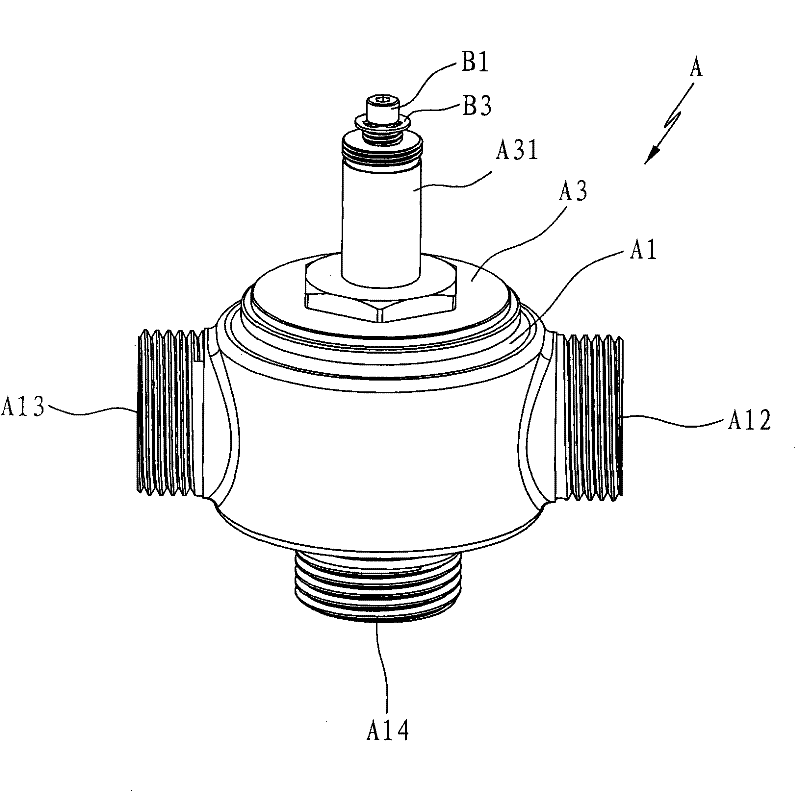
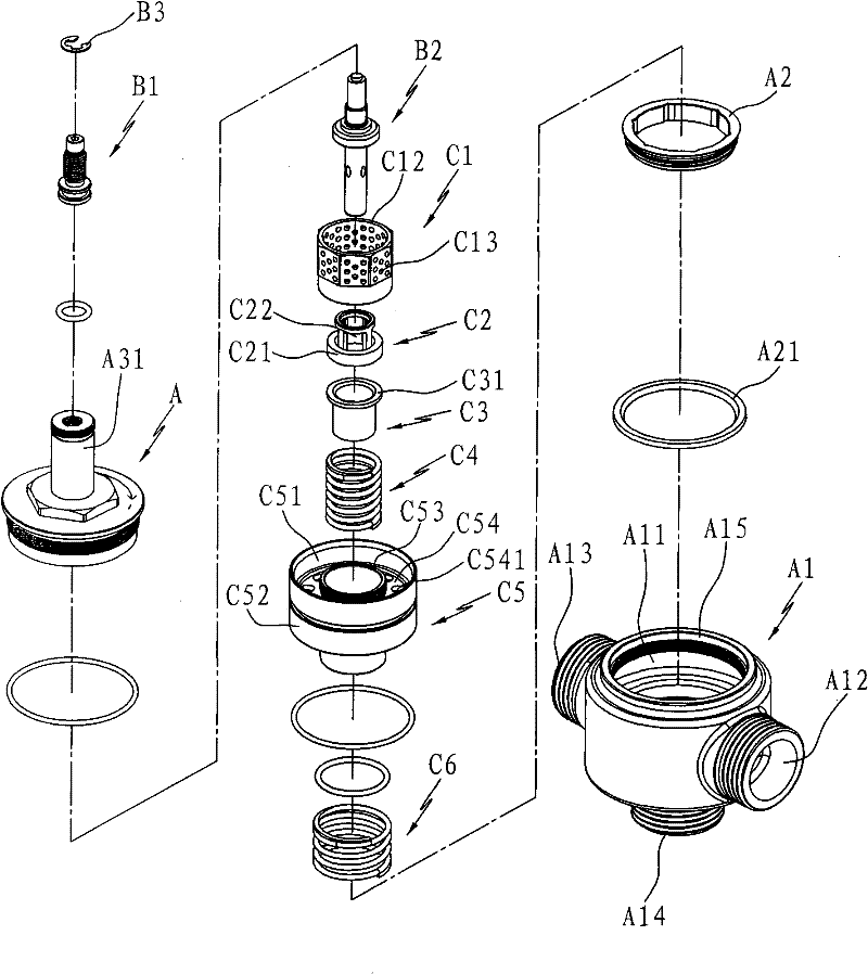
[0026] Such as Figure 1 to Figure 7 As shown, a temperature-controlled mixing valve structure disclosed by the present invention includes a valve body group A, a temperature regulating device B and a constant temperature control device C.

[0027] Cooperate figure 2 , 6 As shown, the valve body group A includes the valve body A1, the gland A2 and the upper cover A3; the valve body A1 forms an inner cavity A11 to accommodate the temperature adjustment device B and the constant temperature control device C, and the valve body is provided with an inner chamber A11. The cold water inlet A12, the hot water inlet A13 and a mixed water outlet A14 connected by the cavity; the gland A2 is a ring cover corresponding to the upper port A141 at the water outlet A14 in the inner cavity A11 of the valve body A1, and the sealing gasket is set therein A21 cooperates with port A141; the section of the sealing gasket is trapezoidal, "丄" shape, "L" shape, "Z" shape or "I" shape. The middle p...


PUM


Abstract

The invention discloses a temperature-controlled mixing valve structure which comprises a valve body assembly, a temperature controller and a constant temperature controller, wherein a reset spring of the constant temperature controller supports a sliding bar assembly which is in dynamic fit with a thermo-sensitive element; the sliding bar assembly comprises a sliding bar, a water mixer, a springpad and a protection spring, wherein the sliding bar is supported between a valve-body upper cover and a mixed water outlet by the reset spring; the sliding bar is provided with an inner sleeve and an outer sleeve, and a water channel is formed between the inner sleeve and the outer sleeve; the upper part of the water mixer is distributed with a plurality of water inlet holes, and the lower part thereof is fixed at the upper end of the inner sleeve of the sliding bar; the spring pad is supported by the protection spring and positioned in the inner sleeve of the sliding bar; the thermo-sensitive element is arranged in the water mixer, the spring pad and the inner sleeve of the sliding bar in sequence in a penetrating way; the upper end of the spring pad is matched with the thermo-sensitivein a contacting way; the upper part of the sliding bar, the upper cover and the external wall of the water mixer form a first water mixing cavity; and the internal wall of the upper part of the watermixer and the external wall of the thermo-sensitive element form a second water mixing cavity. Cold water and hot water are mixed for twice, thus improving the water mixing effect and achieving the purpose of controlling the stability of the water temperature. In addition, a sealing pad is arranged at the hot water end of the valve body, thus improving the performance of losing efficacy of cold water, and realizing excellent safety in use.

Description

technical field [0001] The invention relates to a water outlet valve structure, in particular to a temperature-controlled mixing valve structure for controlling hot and cold water at constant temperature. Background technique [0002] In the sanitary hot water supply system of some special places such as hospitals, nursing homes, kindergartens and nursing homes, it is necessary to strictly avoid the high-temperature hot water from the taps from causing burns to some vulnerable groups such as the elderly, weak, sick, disabled, pregnant and other users . The water outlet valve that controls the constant temperature needs to output water at a stable and reliable constant temperature according to the set value. When the cold water supply is cut off, the temperature of the mixed water should not exceed the initial set value too much to prevent the excessive water temperature from causing harm to the human body; when the hot water supply is cut off When the instant hot water fail...

Claims


Application Information

Patent Timeline
Patent Type & Authority Patents(China)
IPC IPC(8): F16K11/074F16K31/64F16K27/04
CPCG05D23/1346
Inventor 黎克平陈智强
Owner XIAMEN LOTA INT CO LTD
Why Eureka
Try Eureka