Electric probe

An electric and probe technology, which is applied in the direction of measuring electricity, measuring electrical variables, and parts of electrical measuring instruments, can solve the problems of inconvenient measurement, prone to misoperation, and difficult to adjust to a suitable distance, etc., to achieve accurate control, Easy to adjust the effect

Inactive Publication Date: 2010-05-12
刘海先
View PDF0 Cites 13 Cited by
  • Summary
  • Abstract
  • Description
  • Claims
  • Application Information

AI Technical Summary

Problems solved by technology

However, although this kind of test tool is more convenient in operation than the above-mentioned test tool, it does not need to use two hands to adjust the distance between the two probes, but for continuous measurement of multiple electronic devices with different specifications on the circuit board, Frequent manual adjustment of the di

Method used


Image

  • Electric probe
  • Electric probe
  • Electric probe

Examples


Embodiment 1

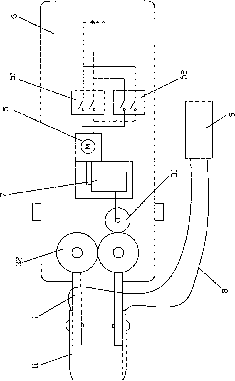
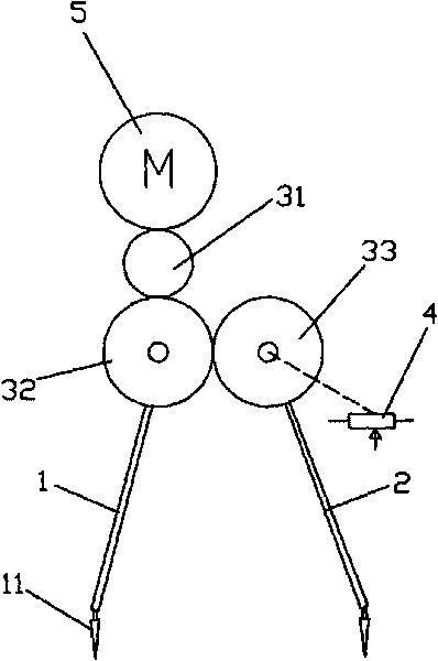
[0024] like image 3 As shown, the electric probe of the present invention includes adjusting arms 1, 2, transmission wheels 31, driving wheels 32, 33 and rotating motor 5, correspondingly setting driving wheels 32, 33 on the adjusting arms 1, 2, driving wheels 32 and driving The wheels 33 are meshed with each other, the driving wheel 32 is meshed with the transmission wheel 31, the transmission wheel 31 is connected with the rotating motor 5, the rotating motor 5 provides power to rotate, and drives the driving wheels 32, 33 to rotate, and then adjusts the adjustment arm connected to it. 1, 2 to adjust the distance between the probe 11 set on the adjustment arm 1, 2. For example figure 2 As shown, the transmission wheel 31, the drive wheels 32, 33 and the rotating motor 5 are all installed in the casing 6, and the casing 6 is also provided with a gearbox 5 connected to the rotating motor, the rotating motor 5 is decelerated by the gearbox 7, and output through the worm Powe...

Embodiment 2

[0028] like Figure 4As shown, the electric probe of the present invention includes adjusting arms 1', 2', transmission wheels 31', driving wheels 32', 33' and rotating motor 5', and the adjusting arms 1', 2' are hingedly connected by two swing rods The two-bar linkage mechanism, one of the heel rods is respectively provided with driving wheels 32', 33', the driving wheels 32' and the driving wheels 33' are meshed with each other, the driving wheel 32' is meshed with the transmission wheel 31', and the transmission wheel 31' is connected with the rotating motor 5', and the other end of the connecting rod on the adjustment arm 1', 2' is provided with a probe, the middle part of which is hingedly connected with the swing rods 34, 36, and the other ends of the swing rods 34, 36 are hinged and fixed on On the electric probe shell, the transmission wheel 31' is powered by the rotating motor 5 to rotate, and drives the driving wheels 32, 33 to rotate, and then adjusts the opening be...

Embodiment 3

[0031] like Figure 5 As shown, the electric probe of the present invention includes adjustment arms 1 ", 2 " and piezoelectric ceramic actuator 5 ", and adjustment arms 1 " and 2 " are connected with two poles of piezoelectric ceramic motor 5 ", and adjustment arms 1 " and 2 " The swing rods 35", 37" are hinged in the middle, and the other ends of the swing rods 35", 37" are respectively hinged and fixed on the shell of the electric probe, and the two ends of the piezoelectric ceramic actuator 5" stretch to drive the adjustment arm 1" and 2" to increase or decrease the distance between them.

[0032] The power mechanism in this embodiment adopts a piezoelectric ceramic actuator to make the distance adjustment between the probes more subtle, and the adjustment arm 1 is properly raised by setting the swing rod 35 ", 37 " in the middle of the adjustment arm 1 ", 2 " The adjustment opening range between " and 2" can effectively measure electronic components of smaller specificat...


PUM


Abstract

The invention discloses an electric probe comprising a probe body, a probe adjusting mechanism and a power mechanism. At least two groups of probe needles are arranged on the probe body, and each group comprises at least one probe needle; the probe body is connected with the probe adjusting mechanism; and the power mechanism is adopted to provide power for the probe adjusting mechanism so as to adjust the distance between the probe needles on the probe body. The electric probe provided by the invention adopts electric power as the power mechanism for driving the distance between the probe needles so as to displace the prior probe which depends on hands and fingers to adjust the distance between the probe needles on the probe. The electric probe has the advantages of convenient adjustment and accurate control, and can be connected with various common testing meters such as oscillometers, LRC element testers and circuit analyzers and the like to form novel testing meters.

Description

technical field [0001] The invention relates to a test tool used in the field of electronic instruments and meters, in particular to a probe for connecting instruments and meters with circuits or devices to be tested. Background technique [0002] Existing test tools for testing electronic devices are two independent test leads or probes. During the measurement of electronic components, the user needs to hold two test leads or probes with both hands, and connect the two test leads or probes with the electronic device to be tested. The endpoints touch and the measurement is made. Due to the different specifications of the electronic components to be tested, it is necessary to adjust the parameters of the instrument while measuring. This kind of test tool with separate design of test leads or probes brings a lot of inconvenience to the measurement of electronic devices. [0003] In response to the above problems, a test tool with two probes connected together has appeared, wh...

Claims


Application Information

Patent Timeline
IPC IPC(8): G01R1/073
Inventor 刘海先
Owner 刘海先
Why Eureka
Try Eureka