Electrical connector locking mechanism
An electrical connector and locking mechanism technology, which is applied in the direction of connection, parts and circuits of the connecting device, etc., can solve the problems of unreliable sealing contact between the plug and the socket, difficulty in the installation and removal of the plug, and low anti-vibration performance of the electrical connector.
- Summary
- Abstract
- Description
- Claims
- Application Information
AI Technical Summary
Problems solved by technology
Method used
Image
Examples
Embodiment 1
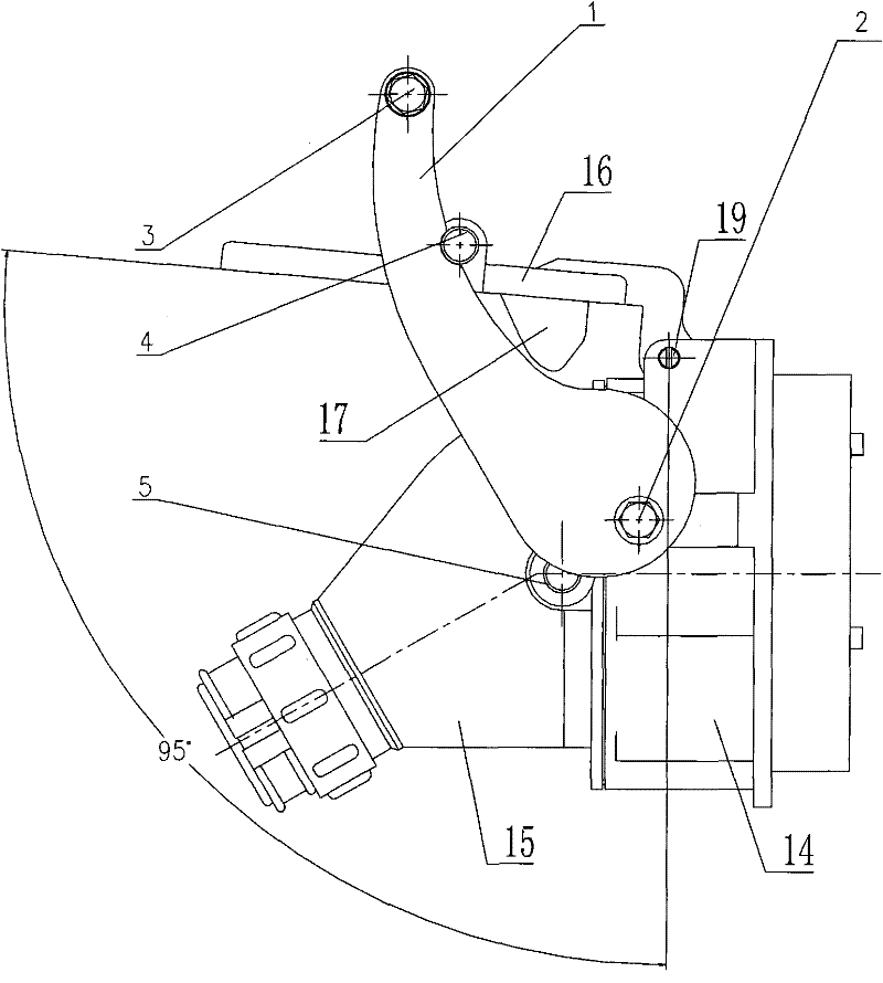
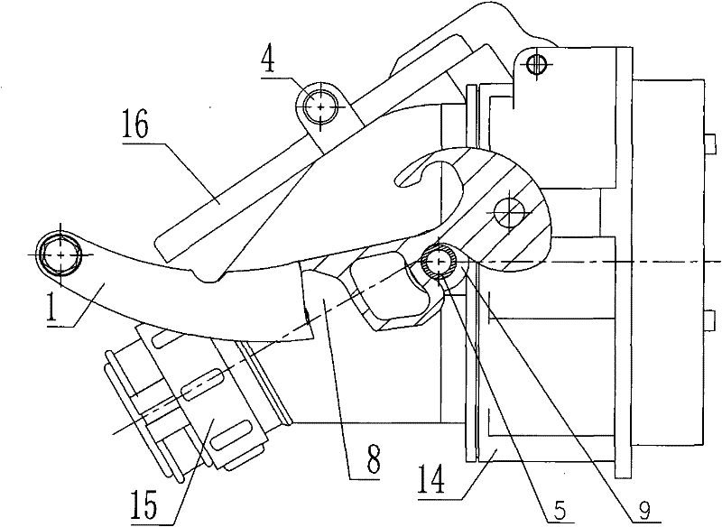
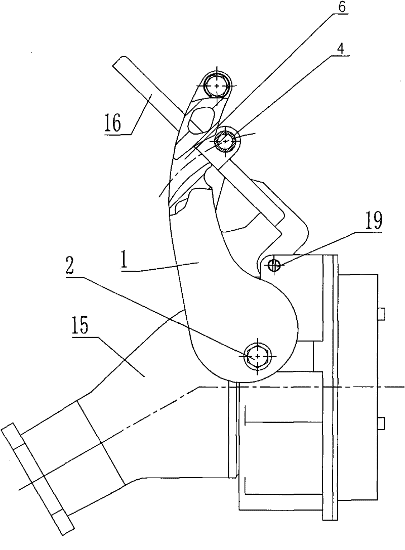
[0021] see Figure 1-7 As shown, the electrical connector includes a socket 14, a plug 15 that is pluggably connected with the socket, and a protective cover 16; the lower surface of the protective cover has a protrusion 17, and when the plug is inserted into the socket, the protrusion can press the corresponding recess 13 on the plug . The protective cover 16 is turned over and connected on the socket by the protective cover shaft 19, and the torsion spring 12 that makes the protective cover turn downwards is sleeved on the protective cover shaft 19 in normal state.
[0022] see Figure 1-6 As shown, the rocker arm locking mechanism of the electrical connector includes two rocker arms 1 , two protective cover locking rollers 4 , two plug locking rollers 5 and a handle 3 . A protective cover locking roller 4 is respectively connected to both sides of the protective cover 16 . Two rocking arms 1 are on both sides of the protective cover, and are parallel to each other, and t...
Embodiment 2
[0029] Example 2 see Figure 5 , 7 , The electrical connector in 8, its plug 15 adopts existing plug (that is, the plug 15 removes the plug locking roller 5 in the embodiment 1). Other structures are with embodiment 1. The locking process when the plug is inserted into the socket:
[0030] Push the handle 3 to make the protective cover locking roller 4 on the protective cover fall into the protective cover positioning groove 7, insert the existing plug into the socket; continue to push the handle 3 to make the protective cover locking roller 4 on the protective cover Slip out from the shifting groove 6 of the protective cover, that is Figure 5 status shown. The protective cover is turned over freely again, and the protrusion 17 falls into the recess 13 on the plug, that is, Figure 7 As shown; push the handle 3 in the opposite direction, so that the first protective cover locking chute 8 on the rocker arm 1 is located above the position of the protective cover locking ro...
PUM
 Abstract
Description
Claims
Application Information
 - R&D
- Intellectual Property
- Life Sciences
- Materials
- Tech Scout
- Unparalleled Data Quality
- Higher Quality Content
- 60% Fewer Hallucinations
Browse by: Latest US Patents, China's latest patents, Technical Efficacy Thesaurus, Application Domain, Technology Topic, Popular Technical Reports.
© 2025 PatSnap. All rights reserved.Legal|Privacy policy|Modern Slavery Act Transparency Statement|Sitemap|About US| Contact US: help@patsnap.com


