

Electronic sport device
A sports device, an electronic technology, applied in sports accessories and other directions, can solve problems such as lack of fun, and achieve the effects of convenient installation, good operability, and small footprint
- Summary
- Abstract
- Description
- Claims
- Application Information
AI Technical Summary
Problems solved by technology
Method used
Image

Examples
Embodiment Construction
[0109] In order to fully understand the technical content of the present invention, the technical solutions of the present invention will be further introduced and illustrated below in conjunction with specific examples, but not limited thereto.
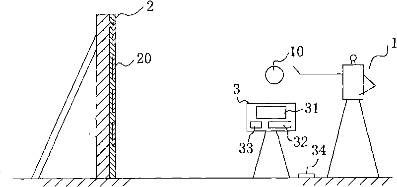
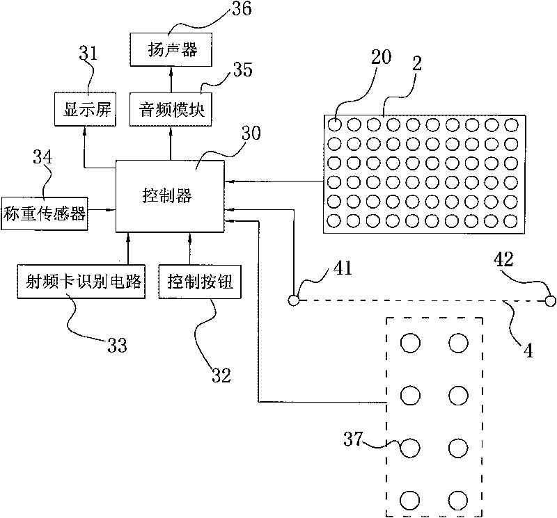
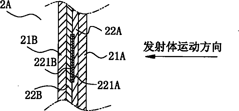
[0110] first from Figure 1 to Figure 7 The structure of an electronic sports device of the present invention is further described. like Figure 1 to Figure 7 As shown, a kind of electronic exercise device of the present invention, comprises the emitter 10 that sportsman 1 sends out, is used for receiving the receiver 2 of emitter 10 (the receiver can also be referred to as receiving member or receiver, is used to receive emitter and a mechanical and electronic component that generates electrical signals) and a controller 30 electrically connected to the receiving device 2; the receiving device 2 is provided with at least one receiving unit 20, and the receiving unit 20 is provided with a switch device electrically connected to the ...
PUM
 Abstract
Description
Claims
Application Information