Floating connector

A connector, floating type technology, applied in the direction of connection, two-part connection device, parts of the connection device, etc., can solve the problem of hindering the movement of the movable shell 120

Inactive Publication Date: 2010-05-19
TYCO ELECTRONICS JAPAN GK
View PDF2 Cites 12 Cited by
  • Summary
  • Abstract
  • Description
  • Claims
  • Application Information

AI Technical Summary

Problems solved by technology

Therefore, in the floating connector 101, if the entire flexible connection portion 113 of each contact 110

Method used


Image

  • Floating connector
  • Floating connector
  • Floating connector

Examples


Embodiment Construction

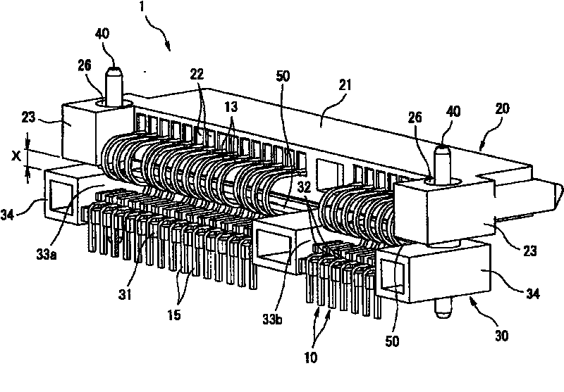
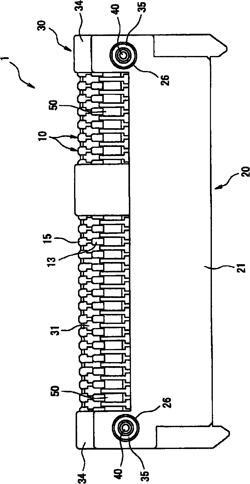
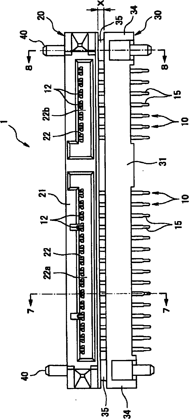
[0065] Next, embodiments of the present invention will be described with reference to the drawings. figure 1 It is a perspective view of the floating connector of the present invention viewed from the back side. figure 2 yes figure 1 Top view of the floating connector shown. image 3 yes figure 1 Front view of floating connector shown. Figure 4 yes figure 1 Bottom view of floating connector shown. Figure 5 yes figure 1 Right side view of floating connector shown. Figure 6 yes figure 1 Rear view of floating connector shown. Figure 7 is along image 3 Sectional view of line 7-7. Figure 8 is along image 3 Sectional view of line 8-8. Figure 9 from the back side figure 1 A partially enlarged perspective view of the floating connector shown. Figure 10 is equipped with figure 1 A perspective view of the contacts and impedance adjustment components on the floating connector shown. Figure 11 is equipped with figure 1 A partial enlarged perspective vi...


PUM


Abstract

A floating connector is provides that enables impedance matching in the entire contact without hindrance of the movement of a movable housing. The floating connector includes a contact, a movable housing, a fixed housing, and an impedance adjusting member. The contact includes a contact portion to be mated with a mating contact, a board connecting portion to be connected to a circuit board, and a flexible coupling portion that is flexible and that couples the contact portion and the board connecting portion. The movable housing receives the contact portion of the contact therein, while the fixed housing secures the board connecting portion of the contact thereto. In addition, the flexible coupling portion includes a first curved portion, a second curved portion, and a linear coupling portion. The second curved portion bends in a reversed direction from a direction that the first curved portion bends, while the linear coupling portion connects the first curved portion and the second curved portion. The flexible coupling portion is formed in such a way to have an S-shape. The impedance adjusting member composed of dielectrics is arranged on the coupling portion.

Description

technical field [0001] The present invention relates to a floating connector, in particular to a floating connector used when two circuit boards are connected to each other. Background technique [0002] Conventionally, as a floating connector used when connecting two circuit boards to each other, for example, there are known Figure 13 The shown floating connector (refer to Patent Document 1). [0003] Figure 13 It is a perspective view of a conventional floating connector viewed from the back side. [0004] Figure 13 The floating connector 101 shown has a plurality of metal contacts 110 , a movable housing 120 , and a fixed housing 130 . [0005] Each contact 110 has: a contact part 111, which is in contact with a counterpart contact provided on a counterpart connector (not shown); a board connection part 112, which is connected to a circuit board (not shown); The connection part 113 connects the contact part 111 and the substrate connection part 112 . [0006] Moreov...

Claims


Application Information

Patent Timeline
IPC IPC(8): H01R24/00H01R13/719H01R13/533H01R13/631H01R13/658H01R13/6477H01R13/648
CPCH01R12/727H01R23/7084H01R13/6315H01R13/646H01R12/7005H01R13/6477H01R23/7005
Inventor 久保晶
Owner TYCO ELECTRONICS JAPAN GK
Why Eureka
Try Eureka