Double-shaft groove forming machine

A trough forming machine and power shaft technology, applied in the direction of earth mover/shovel, construction, etc., can solve the problems of expensive equipment, complex structure, low efficiency, etc., and achieve the effect of ensuring verticality and continuity.

Inactive Publication Date: 2010-05-26
南通同旭贸易有限公司
View PDF0 Cites 14 Cited by
  • Summary
  • Abstract
  • Description
  • Claims
  • Application Information

AI Technical Summary

Problems solved by technology

[0002] At present, most of the trough forming equipment for building underground diaphragm walls have th...

Method used


Image

  • Double-shaft groove forming machine
  • Double-shaft groove forming machine
  • Double-shaft groove forming machine

Examples


Embodiment Construction

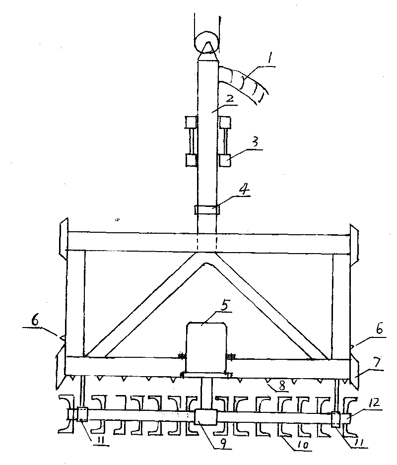
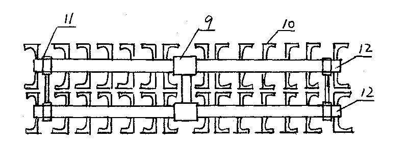
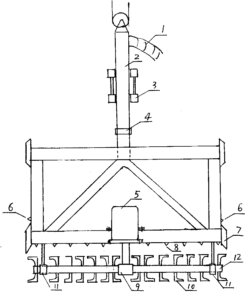
[0015] The accompanying drawing is a specific embodiment of the present invention, which includes a slurry supply system, a guide system and an excavation system.

[0016] 1. Slurry supply system:

[0017] The slurry supply system is composed of a slurry supply hose (1), a slurry supply pipe (2), a water nozzle (8), a side water nozzle (6), a high-pressure mud pump and other pipelines.

[0018] The slurry supplied by the high-pressure mud pump is sprayed out by the water nozzle. The slurry sprayed by the water nozzle and the rotating machete jointly cut the formation and make slurry. The slurry containing mud and sand overflows from the tank and naturally returns to the sedimentation tank, where it settles Finally, the slurry returns to the slurry storage tank, and then the high-pressure mud pump in the slurry storage tank supplies slurry to the tank, and so on.

[0019] The function of the side water nozzle is to wash away the mud partitions on both sides of the double seria...


PUM


Abstract

The invention discloses a double-shaft groove forming machine, which is characterized in that: the bottom end of the groove forming machine is provided with two power shafts (12) which rotate in opposite directions; the power shafts (12) are provided with bent blades; the rotating power of the two power shafts is from a submersible motor (5) in the middle; a water spray nozzle (8) is positioned on a horizontal pipe on the upper side of the power shafts; groove forming slurry is supplied by a high-pressure mud pump, and the slurry passes through a slurry supply hose and a slurry pipe and then is jetted through the water spray nozzle (8); and a guide rail (3) and a guide plate (7) complete the guidance of the groove forming machine together. The double-shaft groove forming machine is a special machine for building underground continuous walls.

Description

1. Technical field: [0001] The invention relates to a groove forming machine, in particular to a double-axis groove forming machine for an underground continuous wall. 2. Background technology: [0002] At present, most of the trough forming equipment for building underground diaphragm walls have the characteristics of shallow trough forming depth, low efficiency, expensive equipment, and complex structure: 3. Contents of the invention: [0003] The present invention makes up for the shortcomings of the above grooving equipment, and provides a double-axis grooving machine with high efficiency, low cost, large grooving depth and simple structure. [0004] The present invention is achieved through the following technical solutions: [0005] A double-shaft grooving machine, which is special in that: the bottom of the grooving machine is equipped with two power shafts (12) that rotate in opposite directions. The rotating force comes from the submersible motor (5) in the midd...

Claims


Application Information

Patent Timeline
IPC IPC(8): E02F5/02E02F5/14
Inventor 张永忠
Owner 南通同旭贸易有限公司
Why Eureka
Try Eureka