Slit antenna, parameter regulation method and terminal thereof

A slot antenna and terminal technology, which is applied in the direction of slot antenna, antenna support/mounting device, circuit, etc., can solve the problems of large size of slot antenna, poor omnidirectional characteristics, large substrate area, etc., to reduce antenna size, increase Effect of number of layers, low resonant frequency

Active Publication Date: 2010-06-02
HUAWEI DEVICE CO LTD
View PDF2 Cites 15 Cited by
  • Summary
  • Abstract
  • Description
  • Claims
  • Application Information

AI Technical Summary

Problems solved by technology

[0004] In the process of realizing the present invention, the inventors found that the prior art has at least the following problems: the current slot antenna radiation has poor omnidirectional characteristics, and the slot antenna has a large size and occupies a large area of ​​the substrate

Method used


Image

  • Slit antenna, parameter regulation method and terminal thereof
  • Slit antenna, parameter regulation method and terminal thereof
  • Slit antenna, parameter regulation method and terminal thereof

Examples


Embodiment Construction

[0030] In order to make the object, technical solution and advantages of the present invention clearer, the implementation manner of the present invention will be further described in detail below in conjunction with the accompanying drawings.

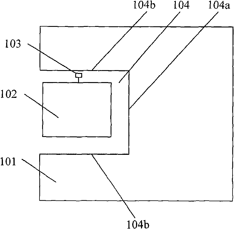
[0031] see figure 2 , this embodiment provides a slot antenna, the slot antenna includes: a floor 101, a coupling piece 102 and a feeding point 103;

[0032] One side of the floor 101 forms a semi-closed grooved area 104;

[0033] The coupling piece 102 is located in the semi-closed slot area 104, and forms a gap with the bottom wall 104a and the side wall 104b of the semi-closed slot area;

[0034] Wherein, the edge of the semi-closed slotted area 104 opposite to the opening of the semi-closed slotted area 104 is called the bottom wall 104a, and the edge of the semi-closed slotted area 104 extending from the bottom wall 104a to the two flanks is called the side wall 104b;

[0035] The feeding point 103 is located in the gap formed ...


PUM


Abstract

The invention discloses a slit antenna, a parameter regulation method and a terminal thereof, which belong to the field of antennae. The slit antenna comprises a floor, a coupling piece and a feeding point, wherein a half-sealed notch area is formed at one side of the floor; the coupling piece is positioned in the half-sealed notch area, and slits are formed among the coupling piece and the bottom wall and the side wall of the half-sealed notch area; and the feeding point is positioned in the slit formed between the coupling piece and the side wall. The method comprises the step of regulating the size of the slit, the size of the half-sealed notch area, the size of the coupling piece and at least one in the number of the layers of the coupling piece so as to obtain a corresponding resonant frequency and a corresponding bandwidth. The terminal comprises the slit antenna. The invention enables current to be evenly distributed on the floor, has better property of omnidirectional radiation, smaller antenna size and smaller occupied area of a basal plate and can retain more areas for arranging other components.

Description

technical field [0001] The invention relates to the field of antennas, in particular to a slot antenna, a parameter adjustment method and a terminal thereof. Background technique [0002] Wireless terminals, especially fixed WLAN (Wireless Local Area Network, wireless local area network) AP (Access Point, access point), WIMAX (Worldwide Interoperability for Microwave Access, global interoperability for microwave access) terminals, wireless fixed stations, etc., need a An omnidirectional radiation, small volume antenna. [0003] At present, there is an antenna formed by opening a slit in the middle of the floor, called a slot antenna. see figure 1 , the typical shape of the slit is elongated, the length is about half a wavelength, and the slit is generally located in the middle of the floor, surrounded by the floor. There is a radio frequency electromagnetic field excited on the gap, and the electromagnetic wave is radiated into the space. After measuring, its horizontal p...

Claims


Application Information

Patent Timeline
Patent Type & Authority Applications(China)
IPC IPC(8): H01Q13/10H01Q1/22
CPCH01Q13/16
Inventor 邹炎炎兰尧孙树辉雷平李正浩班永灵
Owner HUAWEI DEVICE CO LTD
Why Eureka
Try Eureka